Ice making device
An ice-making chamber and refrigerant technology, applied in the field of ice-making devices, can solve problems such as the enlargement of the device
- Summary
- Abstract
- Description
- Claims
- Application Information
AI Technical Summary
Problems solved by technology
Method used
Image

Examples
Example Embodiment
[0043] Example 1
Example
[0044] Hereinafter, the first embodiment of the present invention will be explained based on the drawings.
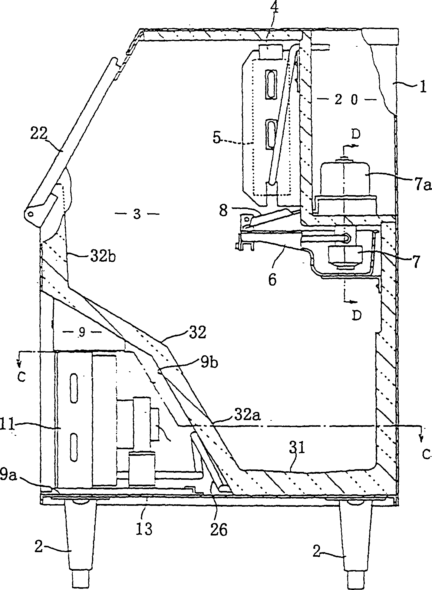
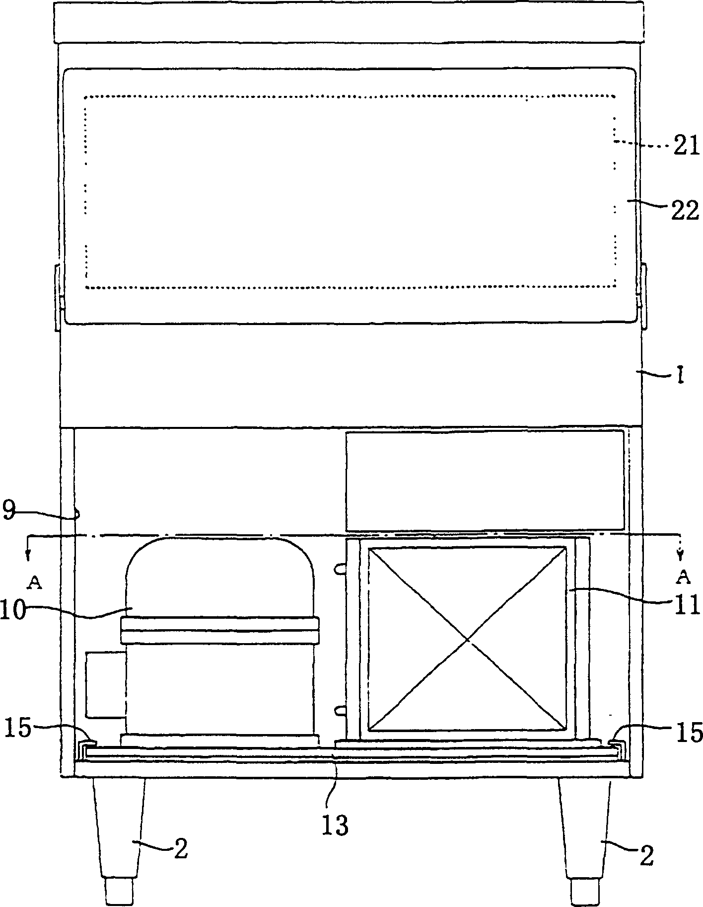
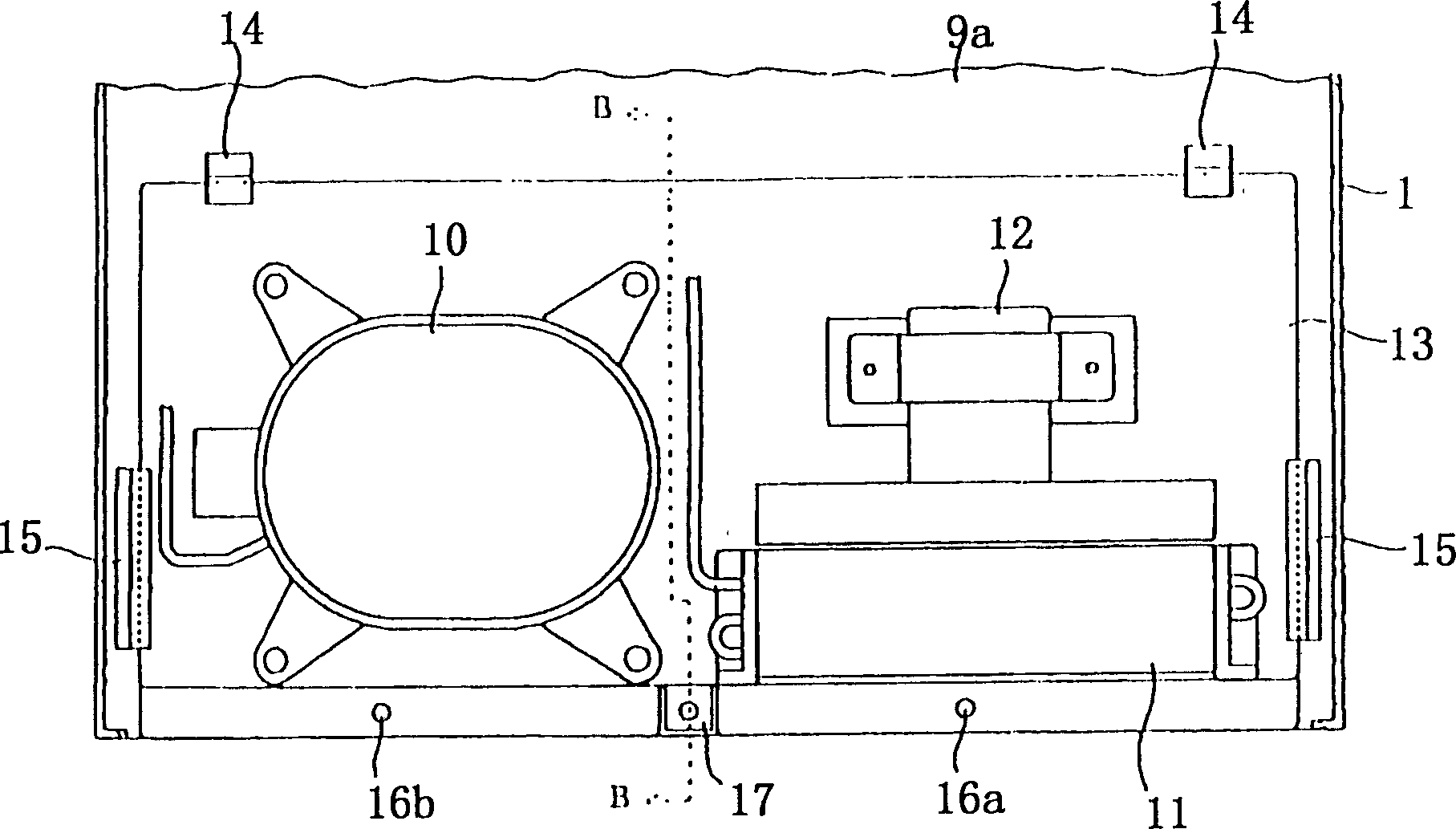
[0045] figure 1 Is a longitudinal cross-sectional view of an ice making device according to an embodiment of the present invention, figure 2 Is its main view, image 3 Is along figure 2 A cross-sectional view along the line A-A.
[0046] Such as figure 1 with figure 2 As shown, an ice making device according to an embodiment of the present invention has a box-shaped main body 1 and a plurality of supporting legs 2 supporting the main body 1 from below, and an ice making chamber 3 is provided inside the main body 1. The ice making compartment 3 has an insulating structure, and the water sprayer 4 and the evaporator 5 are provided inside the ice making compartment 3. The evaporator 5 is arranged below the water sprayer 4 so that the ice making water sprayed from the water sprayer 4 flows down to the surface of the evaporator 5 and is stored in the ice making water tank ...
Example Embodiment
[0060] Example 2
[0061] Hereinafter, a second embodiment of the present invention will be explained based on the drawings.
[0062] Figure 8 Is a longitudinal cross-sectional view of the ice making device of the second embodiment of the present invention, Picture 9 Is its main view, Picture 10 Is along figure 1 A cross-sectional view of line A-A, Picture 11 Is along figure 2 Sectional view of line B-B in the middle.
[0063] Such as Figure 8 As shown, the ice making device of an embodiment of the present invention has a box-shaped main body 101 and a plurality of supporting legs 102 supporting the main body 101 from below. The main body 101 is provided with an ice-making chamber 103 with an insulating structure inside. The ice making chamber 103 is made of heat insulating material, and the water sprayer 105 and the evaporator 106 are provided in the ice making chamber 103.
[0064] The evaporator 106 is arranged at the lower part of the water sprayer 105, and the ice mak...
PUM
 Abstract
Description
Claims
Application Information
 - R&D Engineer
- R&D Manager
- IP Professional
- Industry Leading Data Capabilities
- Powerful AI technology
- Patent DNA Extraction
Browse by: Latest US Patents, China's latest patents, Technical Efficacy Thesaurus, Application Domain, Technology Topic.
© 2024 PatSnap. All rights reserved.Legal|Privacy policy|Modern Slavery Act Transparency Statement|Sitemap