Method and apparatus for an ocean bottom seismic acquisition technique

a seismic acquisition and ocean bottom technology, applied in the field of ocean bottom seismic acquisition technology, can solve the problems of remote control procedure limited by the operational speed and capacity of remote-operated deployment vehicles, seismic survey areas uncovered, and imprecise drift system, so as to improve the coupling of mob instruments, reduce logistic and economic costs, and improve the effect of vector fidelity

Inactive Publication Date: 2005-10-04
WESTERNGECO LLC
View PDF8 Cites 123 Cited by
  • Summary
  • Abstract
  • Description
  • Claims
  • Application Information

AI Technical Summary

Benefits of technology

[0006]The MOBS instruments are self-propelled. The MOBS are guided by a sea-surface and seafloor navigational system, which is well known in the art. A surface vessel communicates with precisely located seafloor navigation buoys and the MOBS to determine the distance between the MOBS, the navigation buoys and the desired location to calculate iterative location commands which are communicated to each MOBS to enable precise navigation commands to steer the MOBS to its desired location. A mechanical system of fins is used to propel the MOBS instruments through a water column. Upon arrival at the ocean bottom, the fins are used to dig into the ocean bottom to improve coupling of the MOBS instruments to the sea floor. As described herein, the ability to affix themselves to the sea floor, in the manner outlined below, provides better coupling of the MO

Problems solved by technology

This drop and drift system is imprecise and potentially leaves seismic survey areas uncovered.
This remotely controlled procedure is limited by the operational speed and capacity of remotely operated deployment vehicles.
Moreover, convent

Method used


Image

  • Method and apparatus for an ocean bottom seismic acquisition technique
  • Method and apparatus for an ocean bottom seismic acquisition technique
  • Method and apparatus for an ocean bottom seismic acquisition technique

Examples


Embodiment Construction

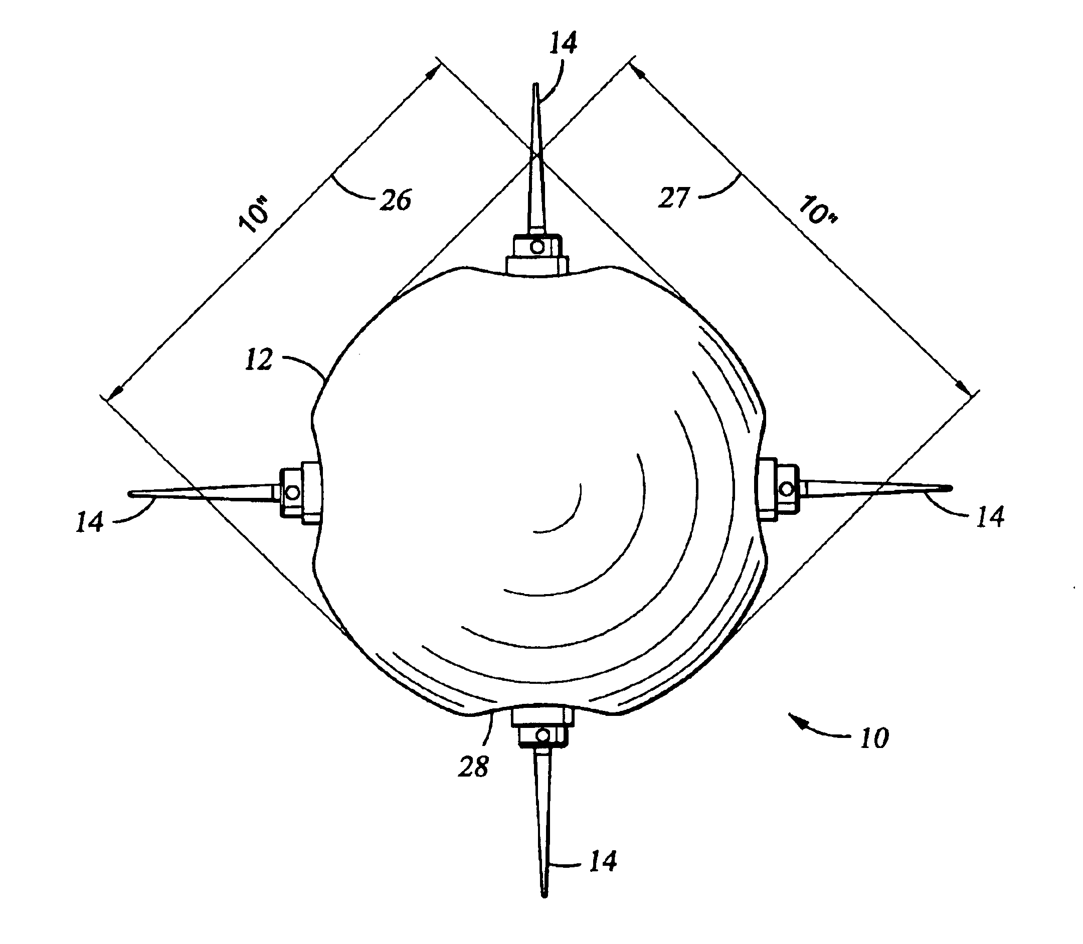
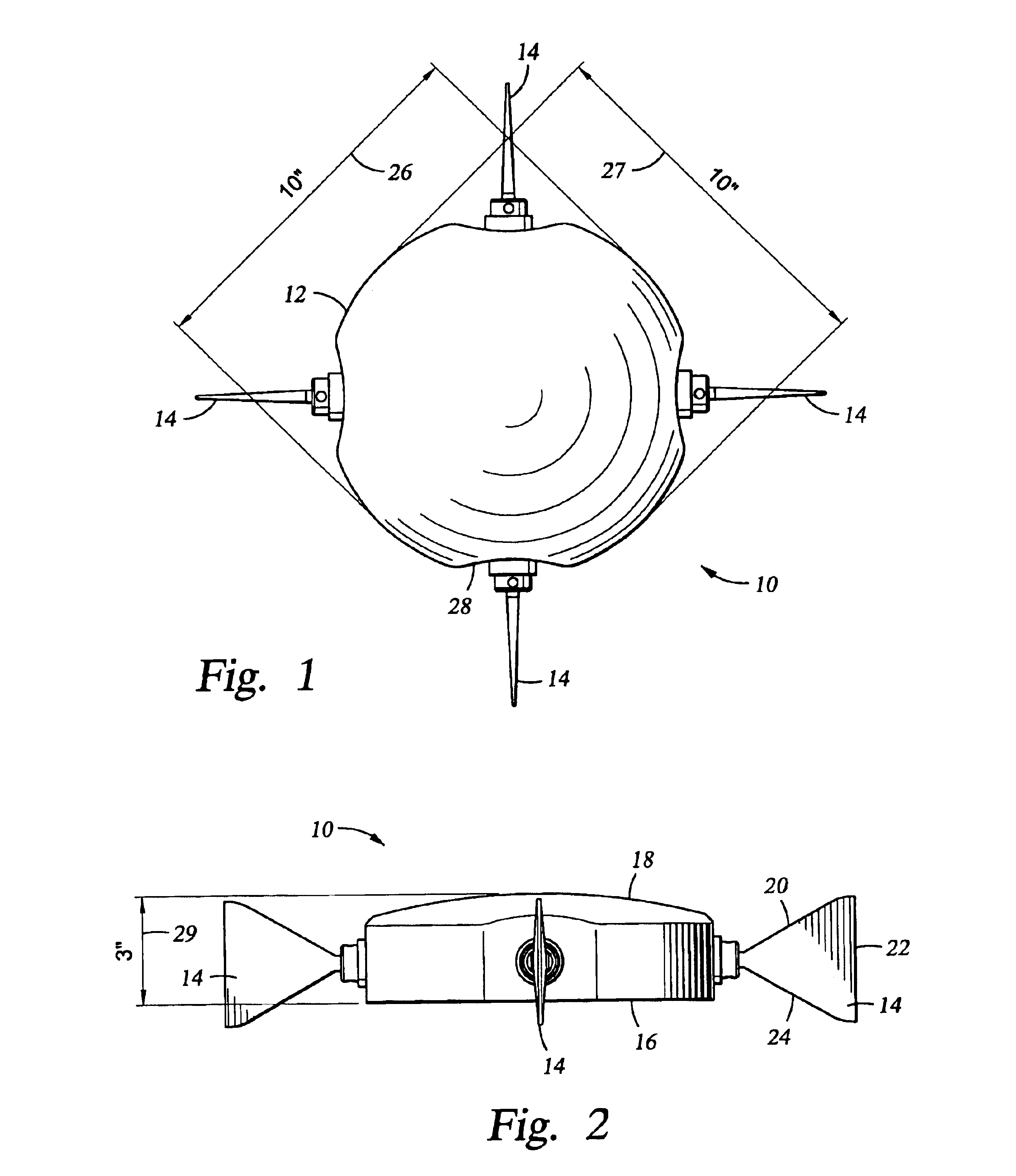
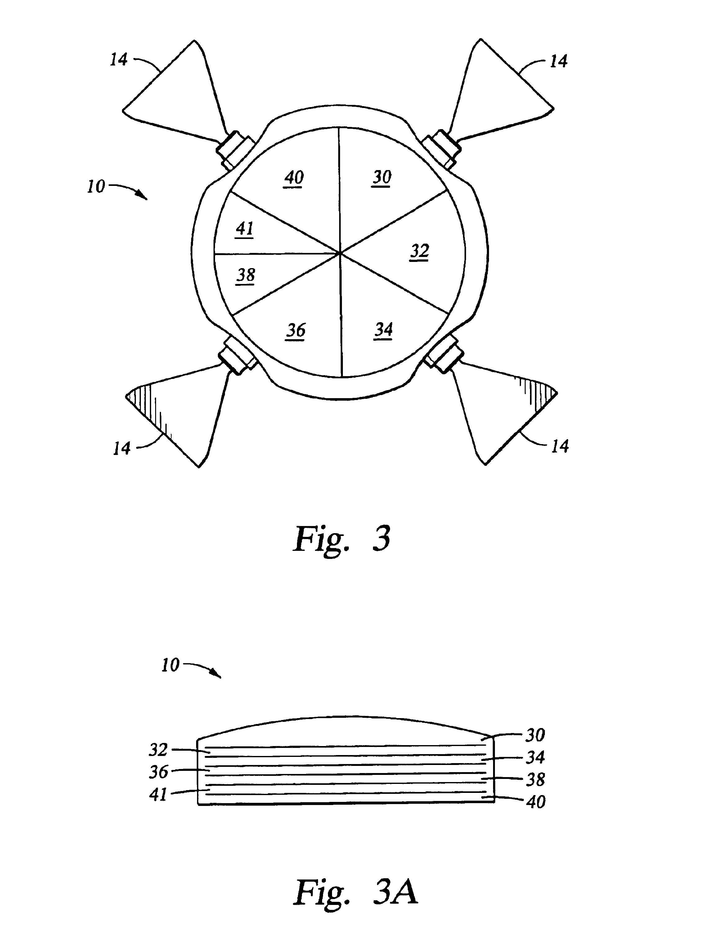
[0014]Turning now to FIG. 1 and FIG. 2, the MOBS 10 provided by the present invention is preferably discoid in shape with a flat bottom 16 and a curved upper surface 18. Any hydrodynamically efficient body shape, however, will work for the present invention. As shown in FIG. 3, the MOBS is schematically compartmentalized into a geophone housing 30, recording housing 32, navigation housing 34, power unit 36, control unit 38, propulsion control unit 40, buoyancy control unit 41 and four propulsion units or fins distributed symmetrically about the geophone frame. FIG. 3A is a side view of the preferred embodiment of the present invention showing that the mass of each MOBS compartment shown schematically in FIG. 3, is equally distributed about the vertical axis of the body or distributed in a balanced fashion so that there is no preferred direction. The preferred dimensions of the instrument are approximately 10.0×10.0×3.0 inches shown by dimension arrows 26, 27 and 29 respectively, as ...


PUM


Abstract

A seismometer having a hydrodynamically efficient shaped body containing a seismic sensor or source, having a propulsion unit located and a control unit for directional control of the propulsion unit for guiding the seismometer to and from an ocean floor. The seismometer can be deployed from a surface ship, helicopter or airplane. The seismometer or surface support vessel contains a navigation unit for directing the control unit to a desired location on the ocean bottom. The apparatus provides a storage device for storing seismic data sensed by the seismic sensor. The navigation system sends a responsive directional command to the apparatus based on the current location and the desired location. Upon arrival at the desired ocean bottom location, the propulsion system acts to couple the apparatus to the ocean floor. A flight control system manages a plurality of the seismometers during navigation to and from the a ocean bottom.

Description

BACKGROUND OF THE INVENTION[0001]1. Field of the Invention[0002]The present invention relates to a system and method for deployment of seismic sensors and in particular to the deployment and retrieval of self-propelled, autonomous seismic sensors in an ocean environment.[0003]2. Description of the Related Art[0004]Historically, ocean bottom seismic data acquisition sensor packaging and deployment has taken the form of either self-contained instruments dropped in the water or sensor cables streamed behind a surface support ship. Typically, self-contained seismic instruments are dropped off the back of a surface support ship where they descend under the influence of their own negative buoyancy to drift down through a water column until they contact the sea-floor. This drop and drift system is imprecise and potentially leaves seismic survey areas uncovered. Typically, the seismic instruments have been deployed from the back of a surface support ship or vessel. Alternatively, surface to...

Claims


Application Information

Patent Timeline
IPC IPC(8): G01V1/16G01V1/38
CPCG01V1/3852G01V1/16
Inventor JONES, NEIL
Owner WESTERNGECO LLC
Why Eureka
Try Eureka