Underwater LED light

a led light and led light technology, applied in the field of underwater led lights, can solve problems such as flooding in the outer compartment, and achieve the effects of reducing the risk of shock to nearby people, efficient removal of heat, and reducing the risk of shock

Active Publication Date: 2006-10-24
HAYWARD IND INC
View PDF39 Cites 124 Cited by
  • Summary
  • Abstract
  • Description
  • Claims
  • Application Information

AI Technical Summary

Benefits of technology

[0006]The present invention overcomes the disadvantages and shortcomings of the prior art discussed above by providing a new and improved underwater light for use in spas, pools, and the like which substantially reduces and / or eliminates the risk of shock to nearby bathers from stray electrical current escaping from the light. More particularly, the underwater light includes a housing, an outer compartment within the housing, a current shield within the outer compartment and at least partially defining an inner compartment within the outer compartment, and a light emitter within the inner compartment. Ordinarily, the housing is water tight, but in the event the housing is no longer watertight (e.g., due to accidental damage to the housing, such as a lens fracture), the outer compartment is subject to flooding by water flowing therein. The underwater light further includes a passageway communicating between the inner and outer compartments such that flood water in the outer compartment can enter the inner compartment and come into contact with the light emitter. The underwater light further includes a conductor positioned so as to collect stray electrical current conducted from the inner compartment by water within the passageway and thereby reduce a risk of shock presented by such stray electrical current.
[0007]In accordance with one aspect of the current invention, the conductor is grounded and includes an electrically conductive surface which at least partially defines the passageway. In accordance with another aspect of the invention, an electrically insulative surface of the current shield is disposed opposite the electrically conductive surface. In accordance with a further aspect of the invention, the underwater light further includes a transformer compartment spaced apart from the inner and outer compartments by a distance sufficiently long so as to permit a free flow of water in a space between the transformer compartment and the inner and outer compartments for efficient removal of heat therefrom.

Problems solved by technology

Ordinarily, the housing is water tight, but in the event the housing is no longer watertight (e.g., due to accidental damage to the housing, such as a lens fracture), the outer compartment is subject to flooding by water flowing therein.

Method used


Image

  • Underwater LED light
  • Underwater LED light
  • Underwater LED light

Examples


second embodiment

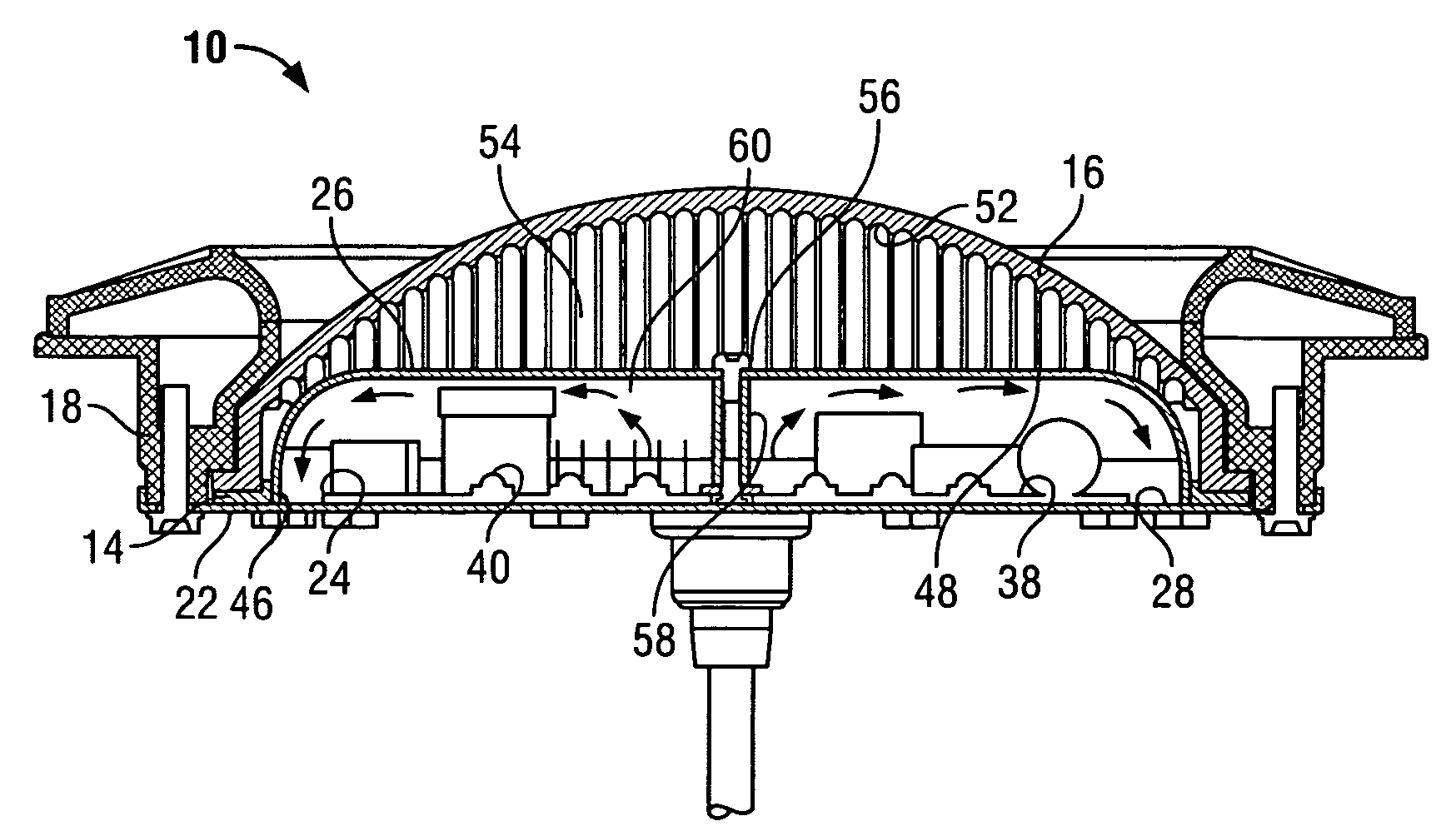
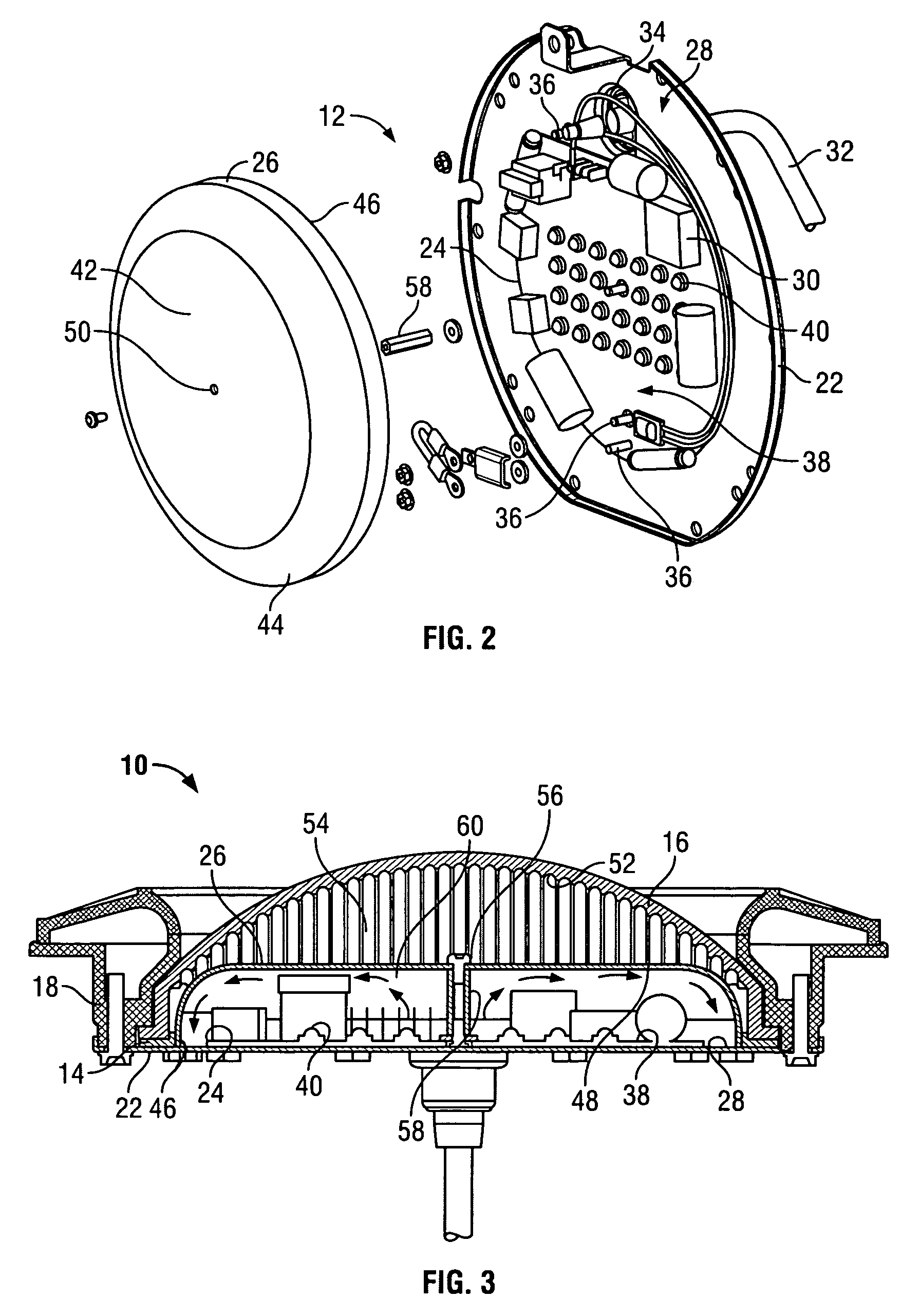
[0035]In FIGS. 5–7, there is shown an underwater light assembly 110 constructed in accordance with the present invention, and suitable for use in a spa. Referring to FIG. 5, in addition to a backplate / PCA assembly 112, a lens gasket 114, a lens 116, a body 118, and a face plate 120, the underwater light assembly 110 includes a separate transformer compartment 168 which includes a base 170 and a rear cover 172 for separately housing a transformer 130, which steps exterior 120V A / C power down to 12V A / C.

[0036]Referring to FIG. 6, the backplate / PCA assembly 112 of FIG. 5 is shown in another exploded assembly perspective view. As shown in FIG. 6, the backplate / PCA assembly 112 includes a backplate 122, a printed circuit assembly 124, and a current shield 126. The backplate 122 includes an interior surface 128 which is both electrically conductive and grounded. The printed circuit assembly 124 is secured directly to the interior surface 128 via thermally conductive adhesive so as to faci...

first embodiment

[0045]It should be noted that the underwater light assembly 110 of the present invention can have numerous modifications and variations. For example, in particular spa lighting applications in which a built-in transformer design is not required, the transformer 130 and the separate transformer compartment 168 can be removed from the underwater light assembly 110 (i.e., similar to the underwater light assembly 10 associated with the present invention, discussed above). In such applications, the underwater light assembly 110 can be supplied with external 12V A / C power (e.g., by the use of a conventional off-the-shelf 120V A / C to 12V A / C transformer mounted in a steel enclosure near the spa) for later conversion to DC power.


PUM


Abstract

An underwater light, e.g., for a pool or spa, includes an ordinarily watertight housing, an outer compartment within the housing and floodable by water flowing therein in the event the housing is no longer watertight, a current shield within the outer compartment and at least partially defining an inner compartment within the outer compartment, a light emitter within the inner compartment, a passageway communicating between the inner and outer compartments such that outer compartment flood water can enter the inner compartment and contact the light emitter, and a conductor. The conductor is positioned so as to collect stray electrical current conducted from the inner compartment by water within the passageway, thereby reducing the risk of shock presented by such stray electrical current. The underwater light is installable within a wet niche, and includes a transformer housed in a separate compartment that extends into the wet niche for thorough cooling thereof.

Description

FIELD OF THE INVENTION[0001]The present invention relates to submergible lights and light fixtures and, more particularly, to underwater LED lights for use in swimming pools and spas.BACKGROUND OF THE INVENTION[0002]Modern designs for swimming pools and spas commonly provide for illumination of the pool or spa from beneath the waterline. For example, underwater light assemblies equipped with glass or plastic external lenses can be installed on and / or in the wall of a pool or spa below the waterline such that part or all of the external lens faces into the pool or spa, and is exposed to the water contained therein. Typically the external lens of such a light at least partially defines a water-tight illumination compartment of the light within which the light-emitting element or light emitter is mounted. While such an arrangement can be advantageous from the standpoint of illumination efficiency, it has long been recognized that such light assemblies can pose a risk of electric shock ...

Claims


Application Information

Patent Timeline
Patent Type & Authority Patents(United States)
IPC IPC(8): F21V29/00
CPCF21V23/005F21V25/00F21V29/30F21S8/00F21V31/005F21W2131/401F21Y2101/02F21Y2105/001F21V23/002F21Y2105/10F21Y2115/10F21V23/006F21V29/56
Inventor WILLIS, VANCE E.GRIFFIN, RONALD H.SHINKAREV, VITALY
Owner HAYWARD IND INC
Why Eureka
Try Eureka