Supercharge Your Innovation With Domain-Expert AI Agents!

Vertical microscope

A microscope, vertical technology, used in microscopes, optics, instruments, etc., can solve problems such as poor operating performance

Inactive Publication Date: 2004-10-27
NIKON CORP
View PDF1 Cites 1 Cited by
  • Summary
  • Abstract
  • Description
  • Claims
  • Application Information

AI Technical Summary

Problems solved by technology

As a result, it is difficult for the user to operate the focus knob and the stage handle with his hand on the table, so the operability is poor

Method used


Image

  • Vertical microscope
  • Vertical microscope
  • Vertical microscope

Examples


Embodiment Construction

[0035] Hereinafter, an upright microscope according to an embodiment of the present invention will be described with reference to the accompanying drawings.

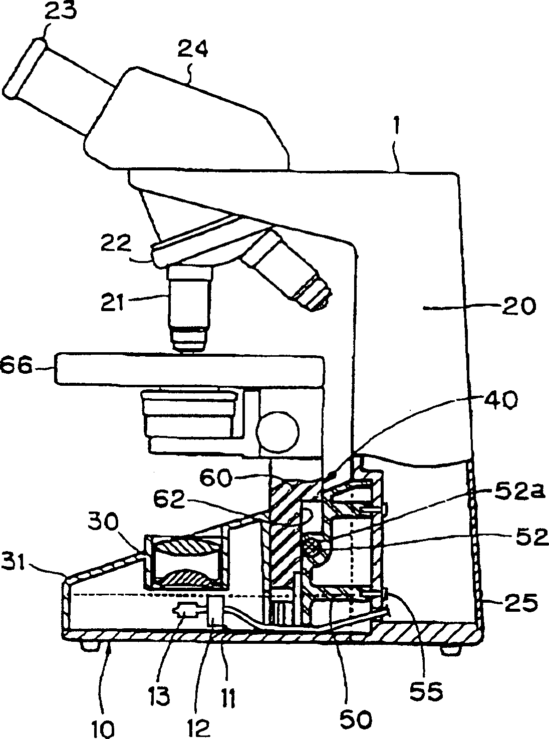
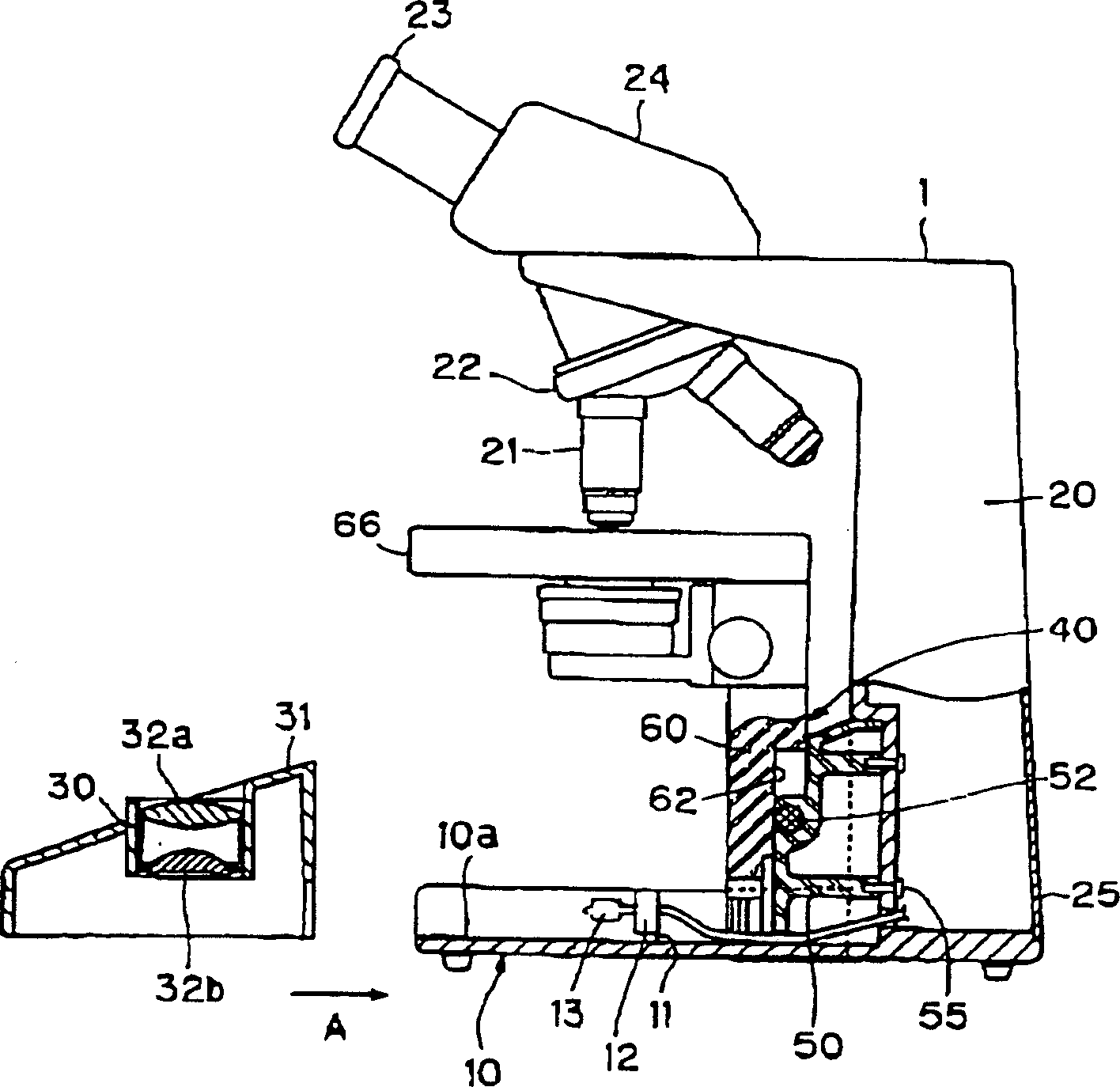
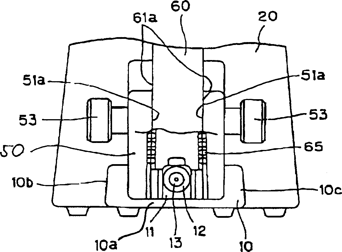
[0036] figure 1 and 2 is a partially cutaway side view showing an upright microscope according to an embodiment of the present invention, image 3 From figure 2 A partially enlarged view of the upright microscope seen in direction A; Figure 4 yes figure 1 A more detailed side view of the upright microscope shown. Figure 5 and Figure 6 yes Figure 4 A perspective view of an upright microscope is shown; it is worth noting that figure 1 and 5 An upright microscope showing the condenser assembly installed, figure 2 and 6 Indicates an upright microscope with a removable condenser lens assembly.

[0037] An upright microscope 1 includes a base assembly 10 , a mirror frame assembly 20 , a condenser lens assembly 30 and a vertical movement assembly 40 .

[0038] The base assembly 10 includes a base plate 10a ...


PUM


Abstract

An upright microscope comprises a microscope main body constituted of a base unit and a stand unit extending upright from the rear end of the base unit. An observation optical system comprising an objective lens and an eyepiece lens is provided at the microscope main body. A stage on which a test piece is placed is assembled into an elevator unit which is caused to move up and down by focusing knobs as an integrated part. The test piece is illuminated by a lamp from below the stage. A recessed portion is formed at the base unit and the lamp is disposed at the recessed portion. The lamp is concealed by a lid member that is attached / detached by sliding over the recessed portion. When the lid member is slid and moved off the base unit, the lamp becomes exposed. As a result, the lamp can be replaced easily.

Description

[0001] Japanese Patent Application No. JP11-188660 filed on Jul. 2, 1999, which is a prior application of this application, is hereby incorporated by reference for this application. technical field [0002] The invention relates to a vertical microscope. Background technique [0003] Figure 11 is a side view of a prior art upright microscope. The upright microscope 101 includes a base assembly 110 , a frame assembly 120 , and a focusing up and down movement mechanism 140 . The base assembly 110 forms an inverted U shape. The bottom of the base assembly 110 is closed by a bottom plate 110a. A light source lamp 113 is disposed in the space S formed by the bottom plate 110a. The light source lamp 113 is located on the optical axis of the objective lens 121 . [0004] The light source lamp 113 is installed on the lamp holder 112 supported by the lamp holder fixing plate 111 . The socket support plate 111 is fixed to an adjustment hole 115 constituting a part of the bottom ...

Claims


Application Information

Patent Timeline
IPC IPC(8): G02B21/00G02B21/08G02B21/24
CPCG02B21/086G02B21/241
Inventor 古桥英彦
Owner NIKON CORP
Features
  • R&D
  • Intellectual Property
  • Life Sciences
  • Materials
  • Tech Scout
  • Unparalleled Data Quality
  • Higher Quality Content
  • 60% Fewer Hallucinations
Learn More