
Hair fixer

A hair clip and hair technology, applied in the field of hair setting, can solve the problems of loss of use feeling, stuck appearance, lack of stuck stability, etc., and achieve the effect of improving the stuck stability

Inactive Publication Date: 2004-11-10
YASUDA KK
View PDF0 Cites 0 Cited by
  • Summary
  • Abstract
  • Description
  • Claims
  • Application Information

AI Technical Summary

Problems solved by technology

In this way, the conventional hair setting tool B lacks the sticking stability, and has the problems of impairing the usability and the sticking appearance.

Method used


Image

  • Hair fixer
  • Hair fixer
  • Hair fixer

Examples


Embodiment Construction

[0033] Hereinafter, it demonstrates based on Example 1 which showed this invention in drawing.

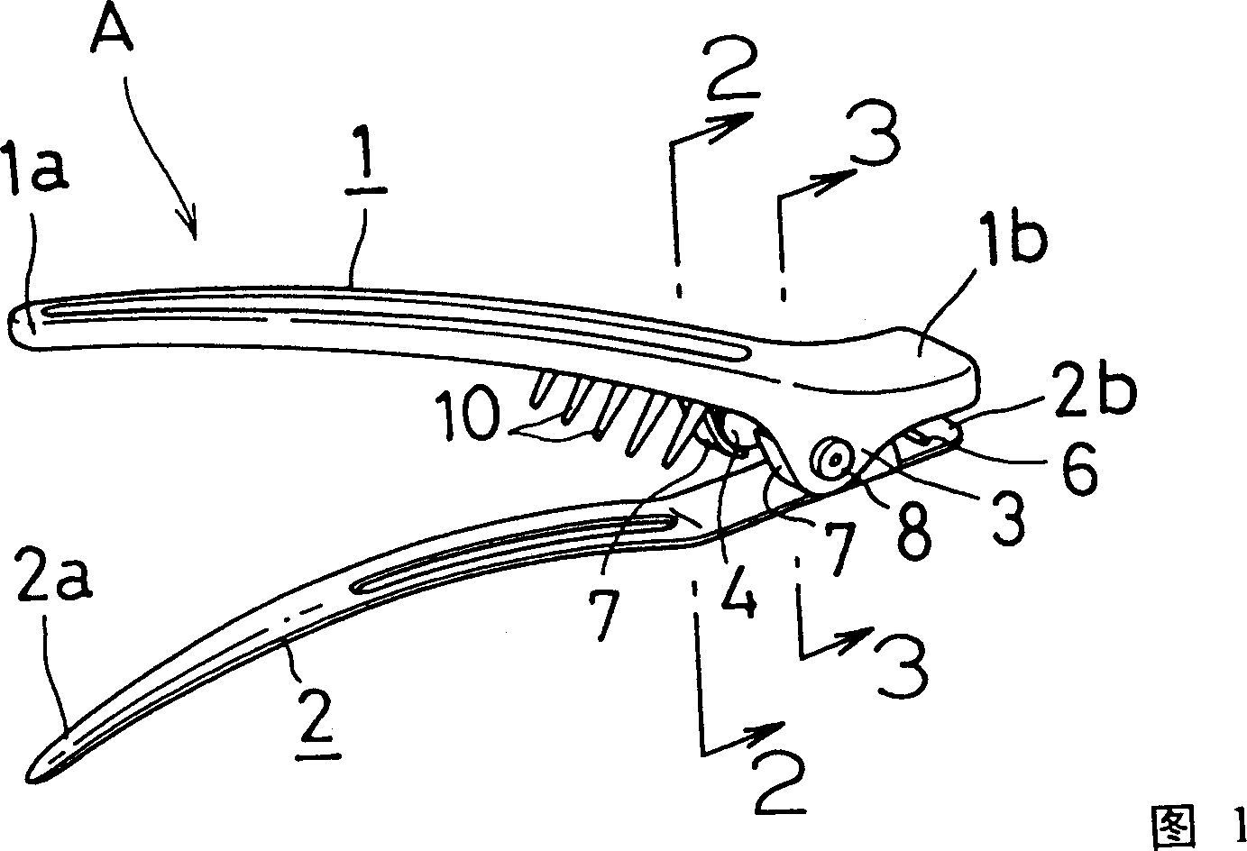
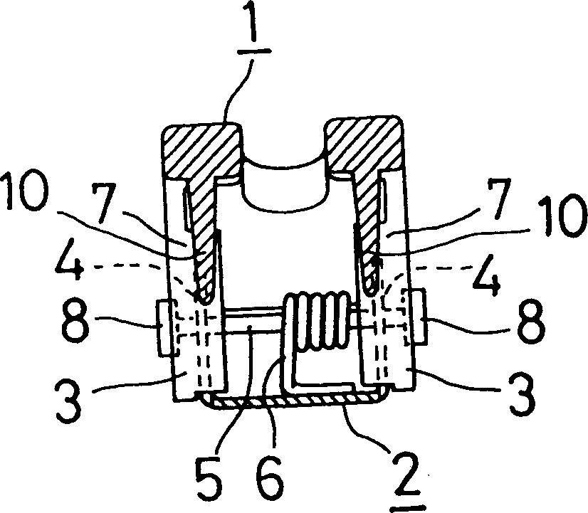
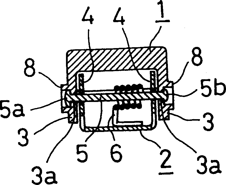
[0034] Such as Figure 4 As shown, the hair setting tool A of this embodiment has a pair of hairpins 1, 2, a shaft 5 and a coil spring 6. The above-mentioned two hairpins 1, 2 are both elongated and strip-shaped materials, and there are handle parts 1b, 2b on one end side in the length direction. In the aforementioned hairpins 1 and 2, in the state where the hairpin A is stuck to the hair, the hairpin 1 located on the outside, hereinafter referred to as the outside hairpin, is molded at one time by semi-hard synthetic resin. In addition, the material of the hairpin 1 is not limited to It can also be made of other various materials such as metal as stipulated in the form of this embodiment.

[0035] The above-mentioned outer hairpin 1 extends downward from the two sides of the above-mentioned one end to have two opposite hinged blades 3, 3, and the pair of hinged blades 3, 3 are res...


PUM


Abstract

The hair fixer is a pair of hairpins. It has two hinged leaves, one of them has one leaf cover to cover the other so as to prevent hair from entering into the interval between two hinged leaves. The outer hinged leaf ahs one cylindrical part with raised lateral side and embedded shaft and this can prevent hair from entering into the interval. In addition, in the inner side of one leaf, there are several lugs to raise the hair clamping force.

Description

technical field [0001] The present invention relates to a hair setting tool with a pair of hair pins which are mutually clamped on the hinged leaves, and the hair is clamped between them. Background technique [0002] Fig. 8 and Fig. 9 show the conventional hair fixing tool B, this hair fixing tool B has a pair of hairpins 51, 52 with handle parts 51b, 52b at one end, these hairpins 51, 52 are embedded with a coil spring 56 at one end, Thus it makes the other ends of the two hairpins 51, 52 always be in the mutually closed state. [0003] Each hairpin 51, 52 has a pair of opposite hinged blades 53, 53, 54, 54 on both sides of the handle portion 51b, 52b. The pair of hinge blades 53 , 53 of one hairpin 51 is disposed outside the pair of hinge blades 54 , 54 of the other hairpin 52 . These hinged blades 53, 53, 54, 54 are installed by the shaft 55 rivets that are wound around the coil spring 56, and at the same time, the other ends 51a, 52a of the two hairpins 51, 52 are alw...

Claims


Application Information

Patent Timeline
Patent Type & Authority Patents(China)
IPC IPC(8): A45D1/06
Inventor 安田昌弘
Owner YASUDA KK
Learn More