
Shaving apparatus

A technology of shearing unit and manufacturing method, which is applied in metal processing and other directions, and can solve problems such as not bringing satisfactory results

Inactive Publication Date: 2004-11-24
KONINKLIJKE PHILIPS ELECTRONICS NV
View PDF1 Cites 0 Cited by
  • Summary
  • Abstract
  • Description
  • Claims
  • Application Information

AI Technical Summary

Problems solved by technology

Gluing the protruding part as an additional plate on the pulling element is an obvious method, however, in practice, this method does not bring satisfactory results

Method used


Image

  • Shaving apparatus
  • Shaving apparatus
  • Shaving apparatus

Examples


Embodiment Construction

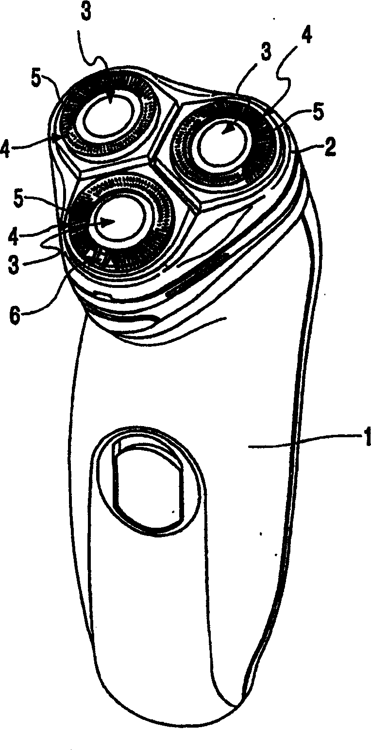
[0015] figure 1 A rotary shaver is shown with a housing 1 and a shaving head holder 2 which is detachable from and / or hinged to the housing. There are three cutting units, also called shaving heads, on the shaving head holder. Each shaving head comprises an outer cutting member 4 with a hair collection opening 5 and an inner hair cutting member 6 driven to rotate relative to the aforementioned elements, the inner hair cutting member is controlled by a An electric motor is driven in a known manner, which is not described in detail.

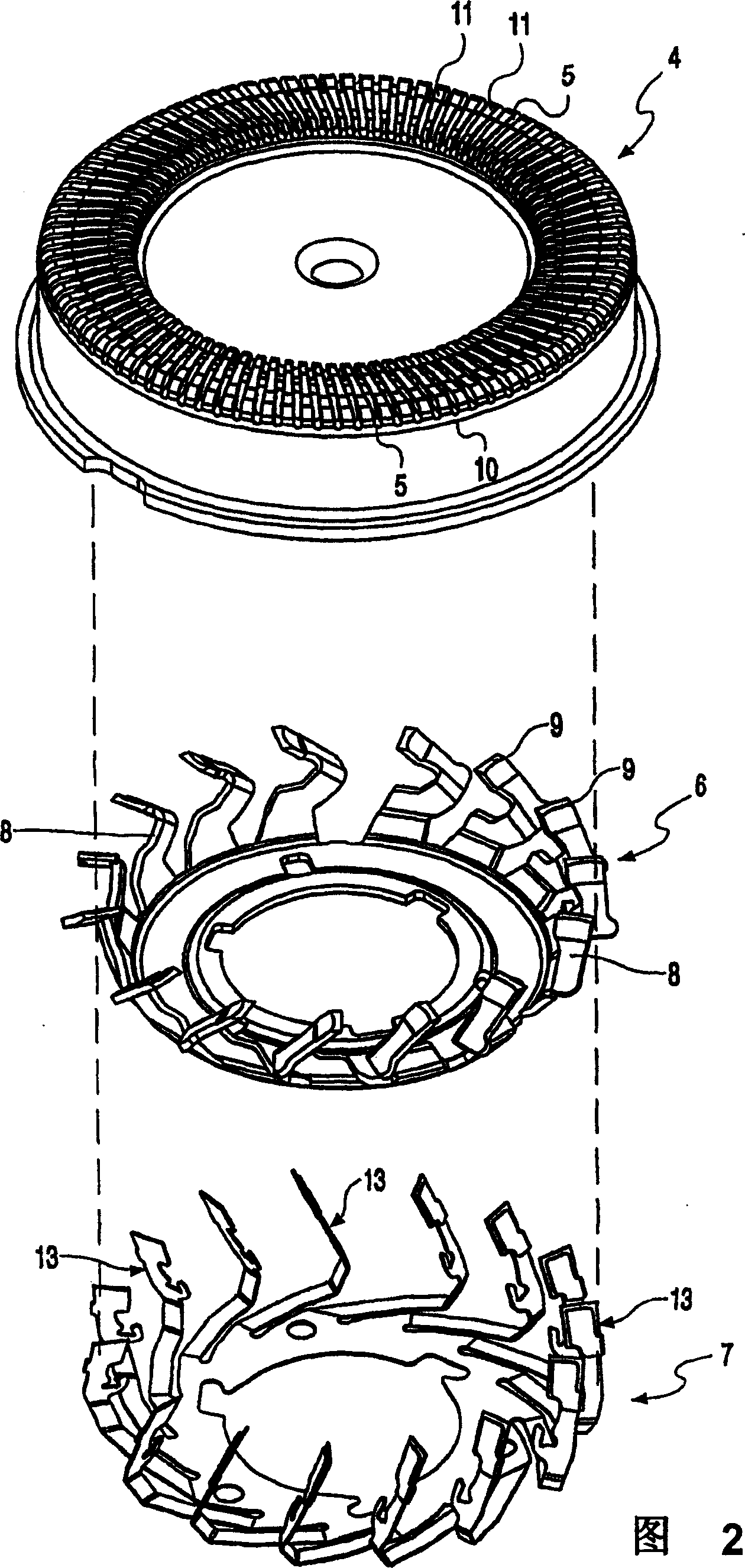
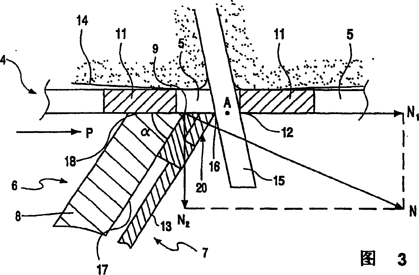
[0016] FIG. 2 shows three parts of the shearing unit 3 , such as an outer shearing element 4 , an inner shearing element 6 and a hair pulling element 7 . The inner shear 6 is a circular body with a plurality of shears 8 each having a cutting edge 9 at its end. The outer shear member 4 shaped as a round cap has a ring wall portion 10, and a plurality of grooved hair collection ports 5 are arranged on the ring wall portion 10. The collection ports...


PUM


Abstract

Method of manufacturing a blade-shaped hair-pulling element (13) for a cutting unit (3) of a shaver. The shaver comprises a plurality of cutter elements (8) and a corresponding plurality of hair-pulling elements (13) each arranged in front of one of the cutter elements for movement therewith relative to an outer cutting member (4) and each slidable on the inner cutter element so as to be movable relative thereto for its hair-pulling action. In order to increase the distance over which the hairs are pulled up, an end portion (22) of each hair-pulling element (13) has an enlarged thickness. The hair-pulling element is obtained by means of a process of shaping the outline (stamping, etching, laser) followed by a bending process. The method to obtain the thickened end part (20) is characterized in that during the process of shaping the outline, the hair-pulling element is provided with a tab (23) which in a following bending process is bent against the end portion (22) of the hair-pulling element.

Description

technical field [0001] The invention relates to a method for the manufacture of a blade-shaped hair pulling element of a shaver cutting unit having an outer shearing element and an inner shearing element drivable relative to said element, said inner shearing element having a design A cutting piece with a cutting edge, and the outer shearing piece is a ring wall portion with a hair collection opening bounded by a counter cutting edge for cooperating with the cutting edge of the driving cutting piece, each The cutting element has a pulling element in a forward position, as seen in the driving direction, which moves back and forth against the annular wall portion of the outer shearing element relative to the connected cutting element during operation of the shaver, while Each hair pulling element has a thickened end with a blade. During operation of the shaver, the thickened end is in contact with the hair extending into the hair collection opening, and when the cutting edge and ...

Claims


Application Information

Patent Timeline
Patent Type & Authority Patents(China)
IPC IPC(8): B26B19/14B26B19/42
CPCB26B19/42B26B19/141
Inventor T·德弗里斯A·J·埃廷克M·阿德里尔安森F·R·沃霍斯特S·E·卡蒂克
Owner KONINKLIJKE PHILIPS ELECTRONICS NV
Learn More