
Method and device for coiling motor stator

A technology of a motor stator and a winding device is applied in the directions of electromechanical devices, manufacturing of motor generators, electrical components, etc., and can solve the problems such as narrow slot openings and scars of the stator 1

Inactive Publication Date: 2005-03-23
NITTOKU ENG CO LTD +1
View PDF1 Cites 0 Cited by
  • Summary
  • Abstract
  • Description
  • Claims
  • Application Information

AI Technical Summary

Problems solved by technology

[0009] However, in the technology disclosed in this Japanese Patent Application No. Hei 11-071246, from the viewpoint of improving motor performance, the slot opening 4 of the stator 1 is extremely narrow, so it is impossible to send out the lead-out pipe 33 from the slot opening 4. The electric wire W is smoothly and surely inserted into the groove 2. In addition, when the electric wire W is inserted into the groove opening 4, the electric wire W is in contact with the protrusion 5 protruding from both sides to the groove opening 4 side. Here, There is a problem of scratches when inserted into the groove 2 while rubbing

Method used


Image

  • Method and device for coiling motor stator
  • Method and device for coiling motor stator
  • Method and device for coiling motor stator

Examples


Embodiment Construction

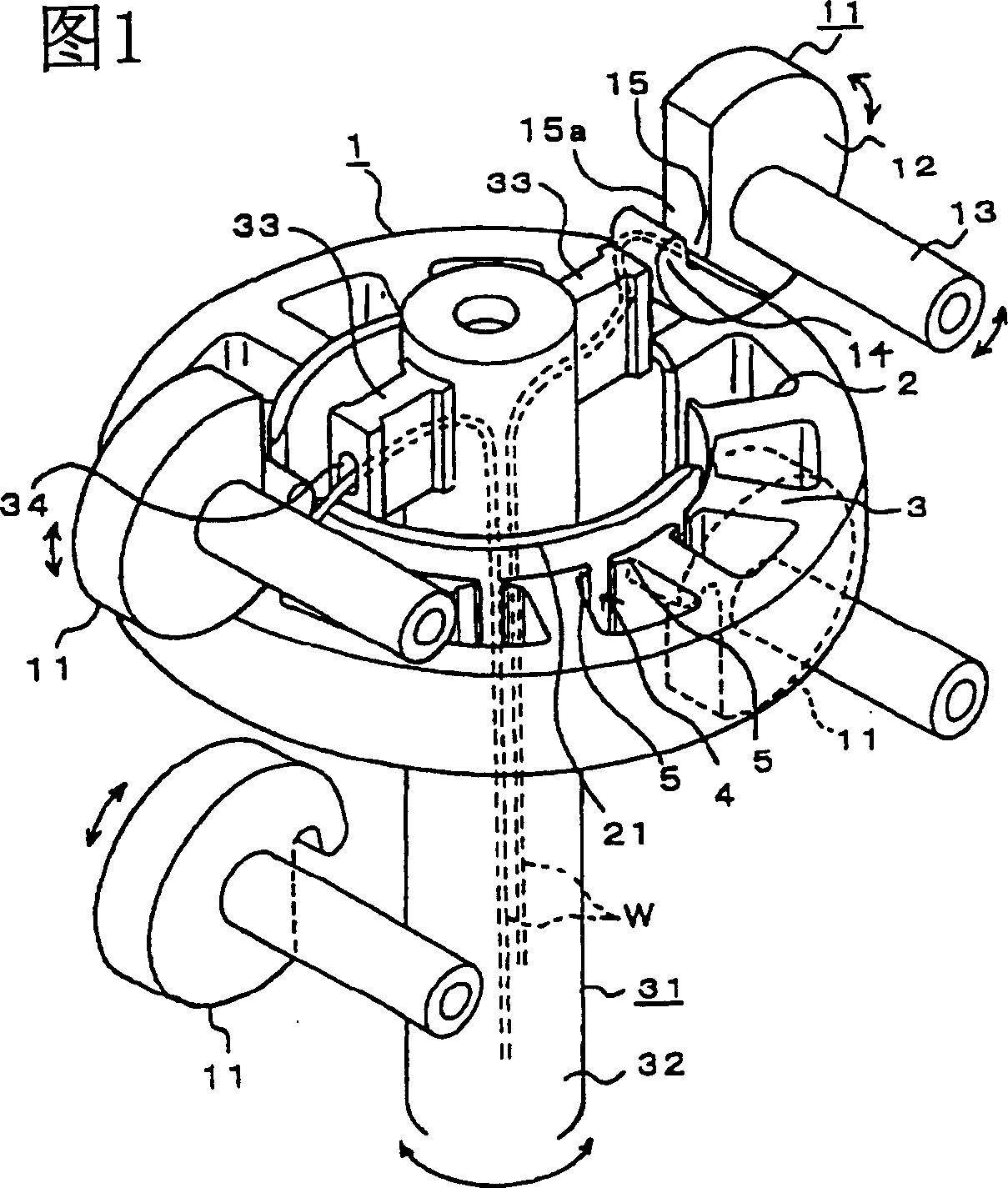
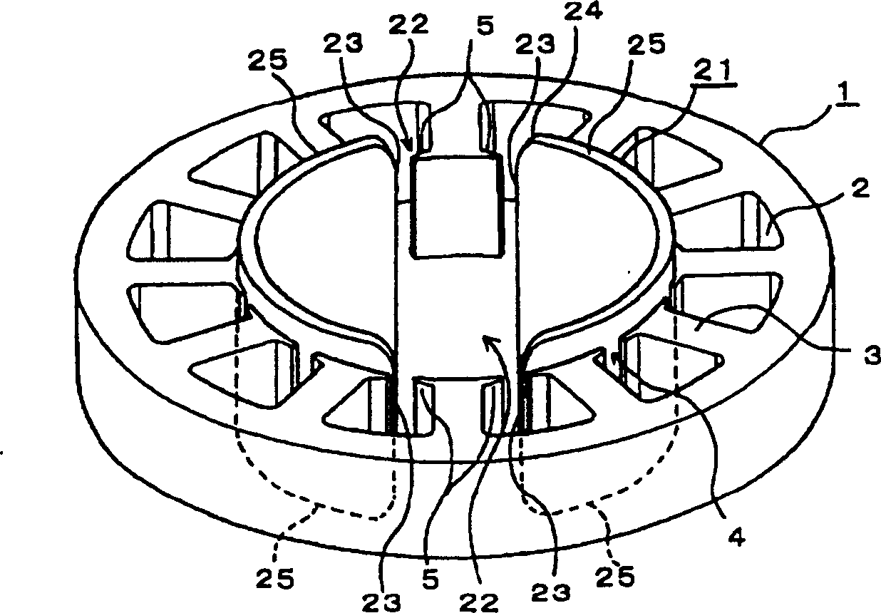
[0034] Below according to Figure 1- Figure 5 A winding device for a motor stator according to an embodiment of the present invention will be described.

[0035] As shown in the figure, the stator 1 of the motor winds the wire W in series on the wound part 3 of the slot 2, as Figure 5 Coils 6 are formed on the respective wound portions 3 as shown. Fig. 1 shows the conveying part of the conveyer 31 of the electric wire W and the wire winder 11 during winding, the shaft 32 of the conveyer 31 is disposed in the central space of the stator 1, and two outlet pipes are arranged radially on the upper part of the shaft 32 33. The above-mentioned protruding length of the outlet pipe 33 can be formed in the central space of the stator 1 with a slight shift away from the slot opening 4 . In the shaft 32 , the electric wire W sent from a winding shaft not shown is inserted therein, and is sent from the opening 34 of the lead-out pipe 33 to the slot 2 of the stator 1 . In FIG. 1 , onl...


PUM


Abstract

A retaining jig is provided comprising a retaining part, a displacing means, a winding machine and a core guide. The retaining part moves together with a nozzle performing a cyclic motion, and holds a wire paid out from the nozzle; the displacing means transports the wire in the outer circumferential direction of a stator while the wire is held; the winding machine has a releasing means which releases the hold on the wire transported to a predetermined position in the outer circumferential direction by the displacing means; the core guide is further disposed opposit to the opening of stator slot, which guides the wire W into the stator when the wire held by the retaining jig is guided in the outer circumferential direction relative to an opening in the stator. A small and high-output motor is obtained by expanding a cross-section area of a coil, eliminating a dead zone in a slot caused by a passing nozzle of a wire supply device, and thereby to smoothly and exactly conduct the winding and inserting of a wire into the slot of a motor stator from an opening of the slot without damaging the wire in particular.

Description

technical field [0001] The invention relates to a winding method and a winding device of a motor stator for eliminating winding dead areas to increase motor output power. Background technique [0002] Figure 15-Figure 18 Shows the existing method of winding the motor stator. [0003] In the figure, the stator 1 winds the electric wire W around the wound portion 3 of the slot 2 . The feeder 31 of the winding device for winding the electric wire W on the wound portion 3 of the groove 2 is provided with a pair of lead-out pipes 33 protruding radially from the upper part of the shaft 32 through which the electric wire W is inserted. The shaft 32 moves through the stator 1 in the axial direction, and performs an oscillating motion of reciprocating and rotating a predetermined angle in the circumferential direction. [0004] In order to wind up the electric wire W using the feeder 31 , the shaft 32 moves up and down in the axial direction and reciprocates in the circumferential...

Claims


Application Information

Patent Timeline
IPC IPC(8): H02K15/095
CPCH02K15/095H02K15/085
Inventor 梶田效
Owner NITTOKU ENG CO LTD
Learn More