Slider for concealed type slide fastener with separable bottom end stop

A code stop, invisible technology, applied in the application, sliding fastener components, fasteners, etc., can solve the problem of not being able to install the bottom end stop smoothly.

Active Publication Date: 2011-02-16
YKK CORP
View PDF1 Cites 0 Cited by
  • Summary
  • Abstract
  • Description
  • Claims
  • Application Information

AI Technical Summary

Problems solved by technology

Thus, if the plunger 128 is inserted from the tooth foot of the slider 101 in a sagging state, the downward facing front end of the plunger 128 contacts the lower pieces 105, 205 of the slider 101, while the curved portion on the top of the plunger 128 Contact is made with the guide grip bend formed on the top of the wedge portion 106 or upper piece 109, 209, so that the engagement collar of the chain element 123 of the adjacent plunger 128 is caught by this portion, and thus the bottom cannot be installed smoothly. end stop code

Method used


Image

  • Slider for concealed type slide fastener with separable bottom end stop
  • Slider for concealed type slide fastener with separable bottom end stop
  • Slider for concealed type slide fastener with separable bottom end stop

Examples


no. 1 approach

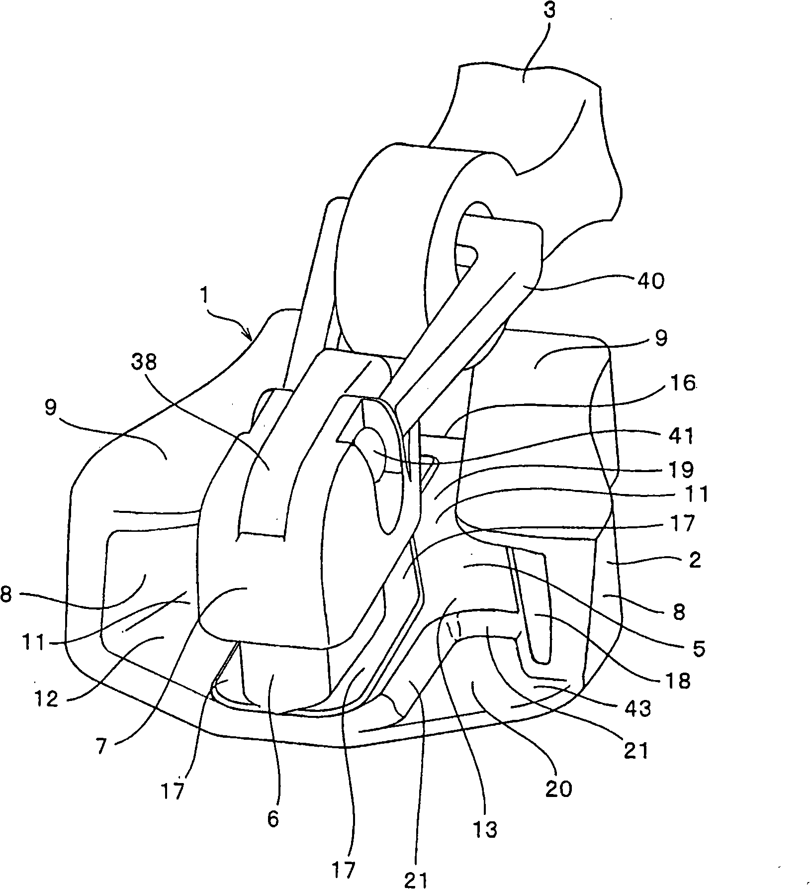
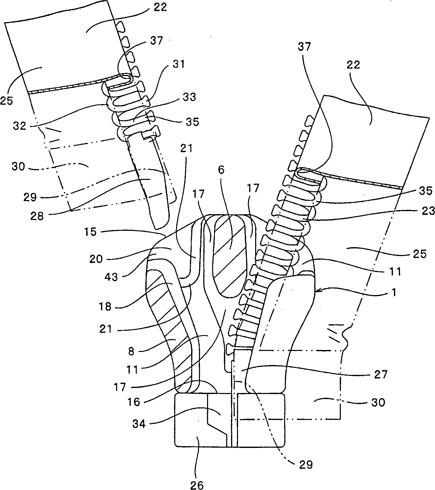
[0046] exist Figure 1 to Figure 7 In the slider for a concealed zipper with a detachable bottom end stop shown in the first embodiment, the main body of the slider 1 and the detachable bottom end consisting of a single socket 26 , seat bar 27 and plunger 28 Stop 4 is made of metal such as aluminum alloy and zinc alloy. In the hidden fastener chain 25 in which the slider 1 passes, the fastener elements 23 are installed along the opposite side edges of the pair of fastener tapes 22 by sewing or the like, and such that the coupling fastener bag 31 is provided inside. A blank portion 29 of the fastener tape 22 in which the fastener elements 23 are not present is provided at one end of the pair of fastener chains 25 , and a reinforcement tape 30 is bonded to the surface thereof. A substantially prismatic seat bar 27 is mounted on the side edge of the blank 29 of one fastener chain 25 adjacent to the fastener elements 23 , while a plunger 28 is mounted on the side edge of the blan...

no. 2 approach

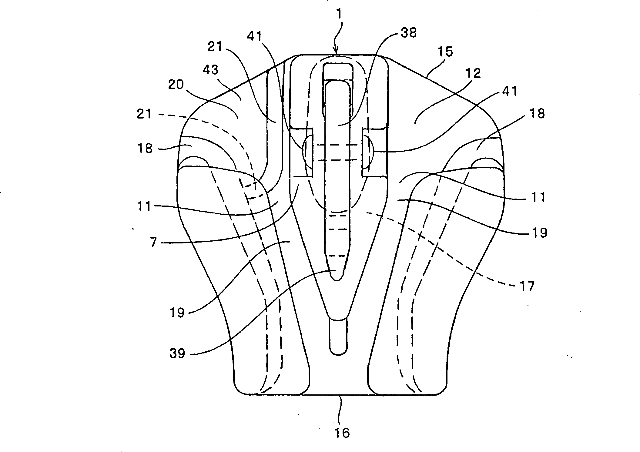
[0058] exist Figure 8 to Figure 10 In the slider for the concealed zipper with a detachable bottom end stop shown in the second embodiment, the wedge part 6 is erected on the lower piece 5 of the main body 2 of the slider 1 so that the wedge part 6 is from the mouth of the teeth The center of 15 extends toward the rear opening 16, and the basic shapes of the handle and bend edges 8 are curvedly provided on both sides of the lower piece 5 are the same as those of the slider 1 of the first embodiment. The second embodiment differs from the first embodiment in that recesses 20 are provided symmetrically on both sides of the wedge 6 in the lower piece 5 of the guide grooves 12 , 13 . The other structures are the same as those of the slider 1 shown in the first embodiment.

[0059] The wedge portion 6 is erected at the center of the tooth foot opening 15 of the lower piece 5, and insertion grooves 12, 13 for inserting the seat rod 27 and the insertion rod 28 are provided on both ...


PUM


Abstract

The present invention provides a slider for a concealed type slide fastener with a separable bottom end stop, capable of, when an insert pin is inserted with an abnormal status, restoring the status to a normal one. In the slider for a concealed type slide fastener with a separable bottom end stop, a recess (20) is provided in a shoulder mouth (15) of a lower blade (5) sideways of a diamond (6) erected from a body (2) of the slider (1) and a slope is formed on a side wall (21) sideways of the diamond (6) and a rear mouth (16) side of the recess (20). Consequently, even if the insert pin (28) is inserted with an abnormal condition, for example, such that the insert pin (28) is drooped in a vertical direction with respect to a fastener tape (22), the slope of the side wall (21) restores thefastener tape (22) into a parallel condition quickly and after that, the insert pin (28) can be inserted into a box (26), thereby attaching the bottom end stop smoothly and easily.

Description

technical field [0001] The present invention relates to a slider for a concealed zipper, which is used in a detachable bottom end stop composed of a socket, a seat bar and a plunger, the detachable bottom end stop being fitted to the teeth of the concealed zipper On the end of the chain, when the slider is operated in the front and rear direction, the detachable bottom stop will separate the tooth chain in the closed state into left and right tooth chains and close the tooth chain in the open state. Slider for concealed zippers with detachable bottom stop for the insertion capability of the rod into the slider. Background technique [0002] In conventionally known sliders for concealed zippers with detachable bottom stops, as shown in FIGS. , and a pull tab mounting portion 107 with a locking mechanism is provided on the top of the wedge portion 106, although the locking mechanism is not shown in the figure. The pull tab mounting portion 107 extends laterally on the wedge ...

Claims


Application Information

Patent Timeline
Patent Type & Authority Patents(China)
IPC IPC(8): A44B19/26A44B19/34
CPCA44B19/26Y10T24/2582Y10T24/2561Y10T24/2591Y10T24/258
Inventor 高荷刚小泽贵敬
Owner YKK CORP
Why Eureka
Try Eureka