Cutter

A tool and tool arm technology, applied in the field of tools with a safety device, can solve the problems that it is difficult to observe the cutting part and the cutting work is difficult

Inactive Publication Date: 2005-04-06
CARL JIMUKI
View PDF0 Cites 0 Cited by
  • Summary
  • Abstract
  • Description
  • Claims
  • Application Information

AI Technical Summary

Problems solved by technology

[0003] However, in a conventional tool 55, since the arm 51 is fixedly mounted on the handle 52 or integrally formed with the handle, and, for example, when the workpiece to be cut is to be cut in a straight line, as Figure 15 Shown, in order to make the rotary blade 53 move along a straight line, the cutting work is carried out by making the knife arm 51 remain at an angle of 45 degrees with respect to the cutting surface 54. Having to bend his wrist or lift his elbow is a burden on him
Moreover, cutter 55 is generally provided with a guard as a safety device for the cutter of rotary blade 53, which is constructed in such a way that guard 56 is arranged on one side of rotary blade 53 so that the guard 56 56 slides itself to extend or retract, or the rotating blade 53 moves itself so that the cutter of the rotating blade 53 slides to play a protective role, but for a left-handed person, because his line of sight is cut off by the guard 56, it is very difficult It is difficult to observe the cutting part, making cutting work difficult

Method used


Image

  • Cutter
  • Cutter
  • Cutter

Examples


Embodiment Construction

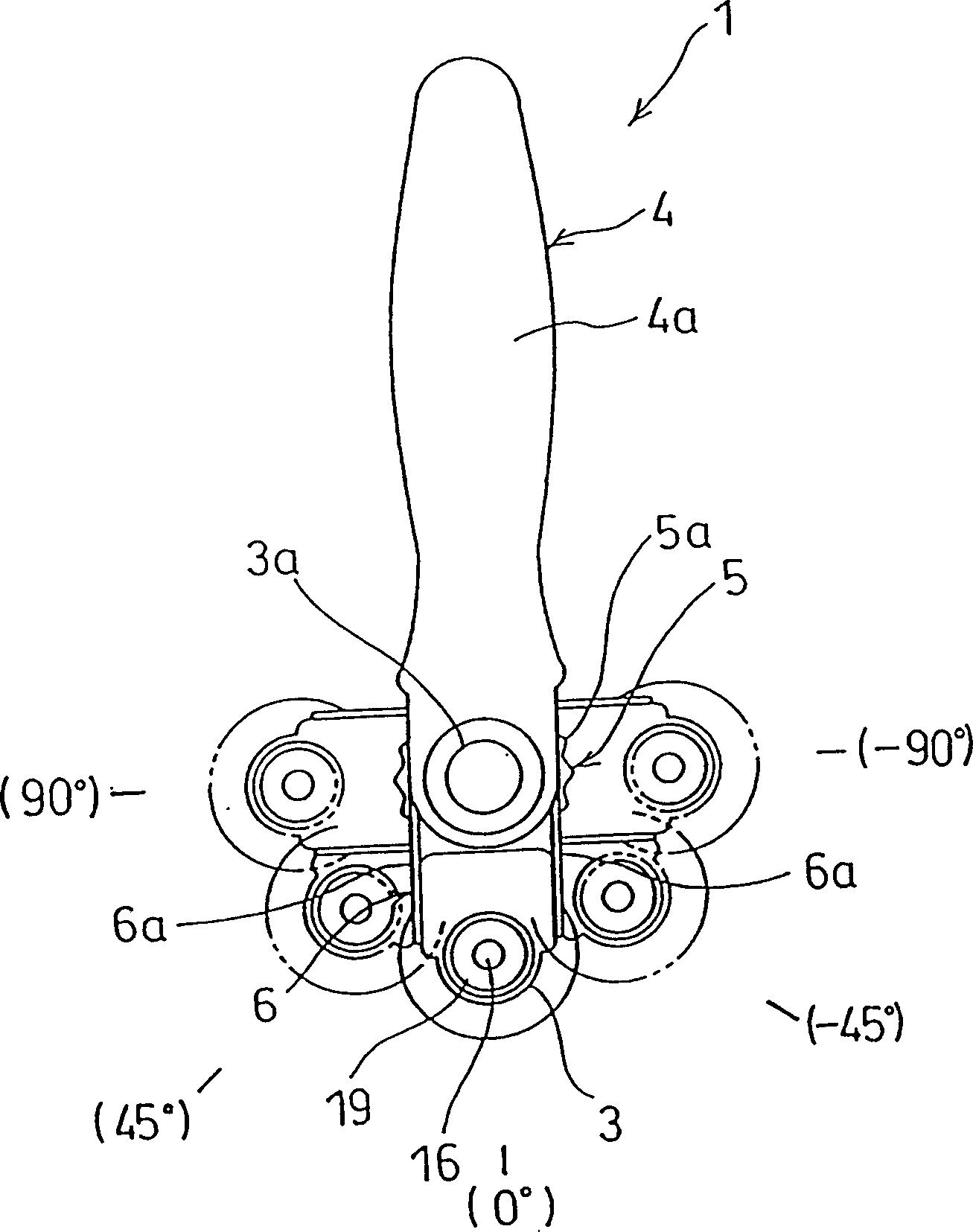
[0027] Embodiments of the cutting tool of the present invention will be referred to Figure 1-14 to explain. First, an overview of the cutter of this embodiment will be given. like figure 1 As shown, the knife 1 of this embodiment includes a knife arm 3 pivotally connected with a rotating blade 2 and a knife handle 4 clamping the knife arm 3, and by pressing the button 3a, the knife arm 3 can be wound around the support of the knife arm 3 The shaft turns and is fixed (or positioned) every 45 degrees. Moreover, the tool 1 is provided with a guard 6, which can move forward or retract backward by rotating a turntable formed on the guard driver 5 (to be explained later), and retract when the guard 6 retracts. state, that is, when the cutter of the rotating blade 2 is not protected, the button 3a will be locked and the rotation of the knife arm 3 will be restricted.

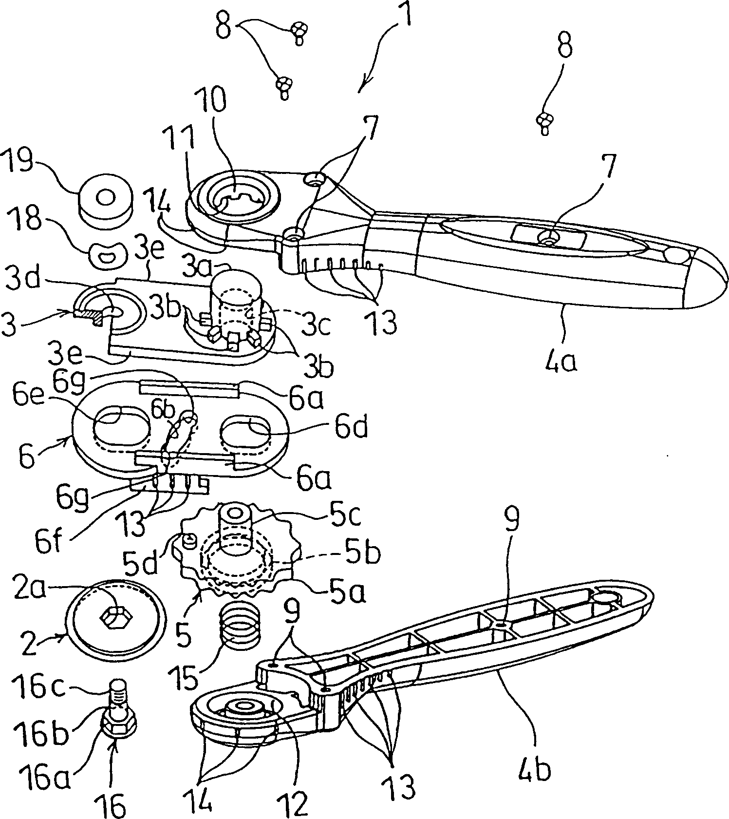
[0028] Next, each constituent part of the tool 1 is explained in detail. like figure 2 As shown, the knife ...


PUM


Abstract

Around a push button formed on an arm 3, teeth are disposed at a regular angle, and around the push button inserting hole in a handle 4 grooves 11 are disposed corresponding to the teeth, thereby, by biasing the arm 3 with a compressed coil spring to engage the teeth with the grooves. Whereby, by pushing the push button to cause the arm to stroke, the engagement of the teeth and the groove is released to cause the arm 3 to turn and by freeing the push button the teeth and the grooves are engaged, thereby the arm 3 is positioned and held at a desired position.

Description

technical field [0001] The present invention relates to a knife equipped with a rotating blade, in particular a knife with a safety device. Background technique [0002] like Figure 15 As shown, a tool includes a tool arm 51 and a tool handle 52 on which an annular cutter is rotatably mounted (hereinafter referred to as a rotary blade), and forms such a structure that when it is on the workpiece to be cut Top edge of cutting surface Figure 15 When the direction of the arrow A in the rotating blade is operated to cut the workpiece to be cut into a desired shape, the rotating blade 53 is pressed at the same time. When cutting a workpiece to be cut with the cutter 55, it is easy to move the rotary blade linearly by holding the cutter 55 at an angle, that is, the angle formed between the cutter arm 51 and the cutting face 54 ( Figure 15 θ) is 45 degrees, and it is now known that as the angle formed between the arm 51 and the cutting surface 54 ( Figure 15 Where θ) is reduced...

Claims


Application Information

Patent Timeline
Patent Type & Authority Patents(China)
IPC IPC(8): B26B25/00B26B29/02
CPCB26B25/005B26B29/02
Inventor 森诚吴小东
Owner CARL JIMUKI
Why Eureka
Try Eureka