Integrated fillet weld stir friction welding tool and method

A friction stir and welding tool technology, applied in welding equipment, manufacturing tools, non-electric welding equipment, etc., can solve the problems of low clamping efficiency and complex structure of stirring tools, achieve high coaxiality, reduce complexity, and realize modularization the effect of

Active Publication Date: 2019-03-01
SHANGHAI AEROSPACE EQUIP MFG GENERAL FACTORY
View PDF6 Cites 9 Cited by
  • Summary
  • Abstract
  • Description
  • Claims
  • Application Information

AI Technical Summary

Problems solved by technology

However, the structure of the device is complex, and it is necessary to process the static shoulder installation interface at the corresponding position of the machine tool spindle.
At the same time, due to the split structure between the stirring needle and the shaft shoulder, the two need to ensure a high degree of coaxiality during welding, which requires high assembly precision, resulting in low clamping efficiency of the stirring tool

Method used


Image

  • Integrated fillet weld stir friction welding tool and method
  • Integrated fillet weld stir friction welding tool and method
  • Integrated fillet weld stir friction welding tool and method

Examples


Embodiment Construction

[0017] In order to describe the technical content, structural features, and achieved goals and effects of the present invention in detail, the following will be described in detail in combination with embodiments and accompanying drawings.

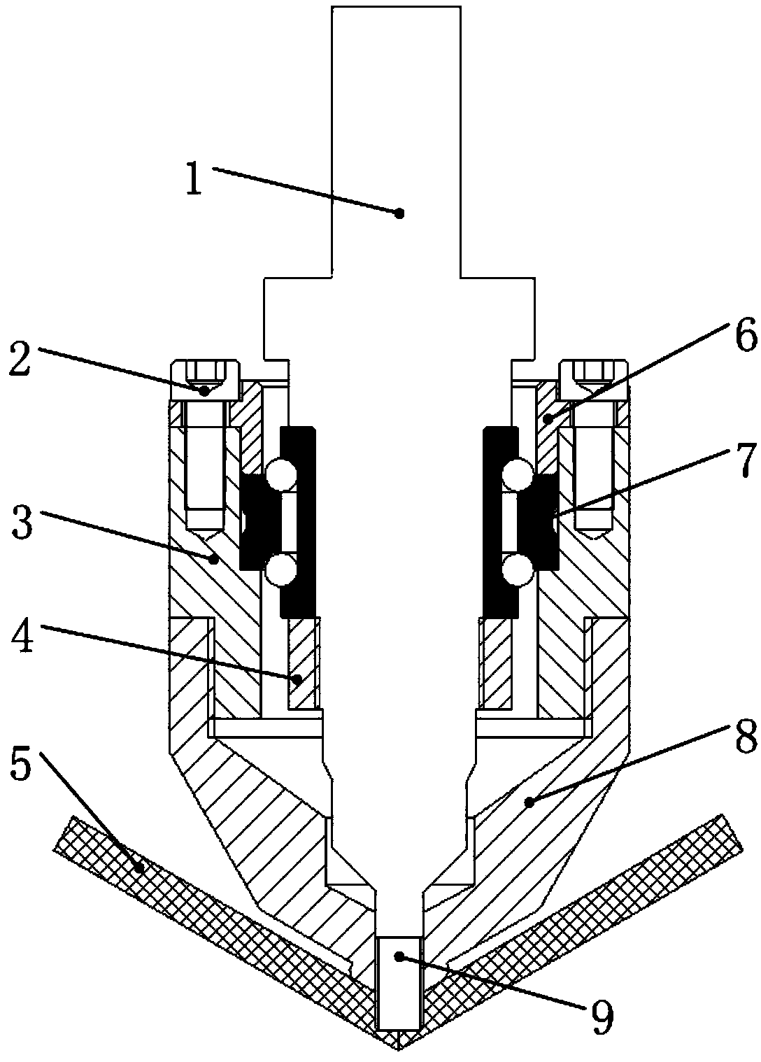
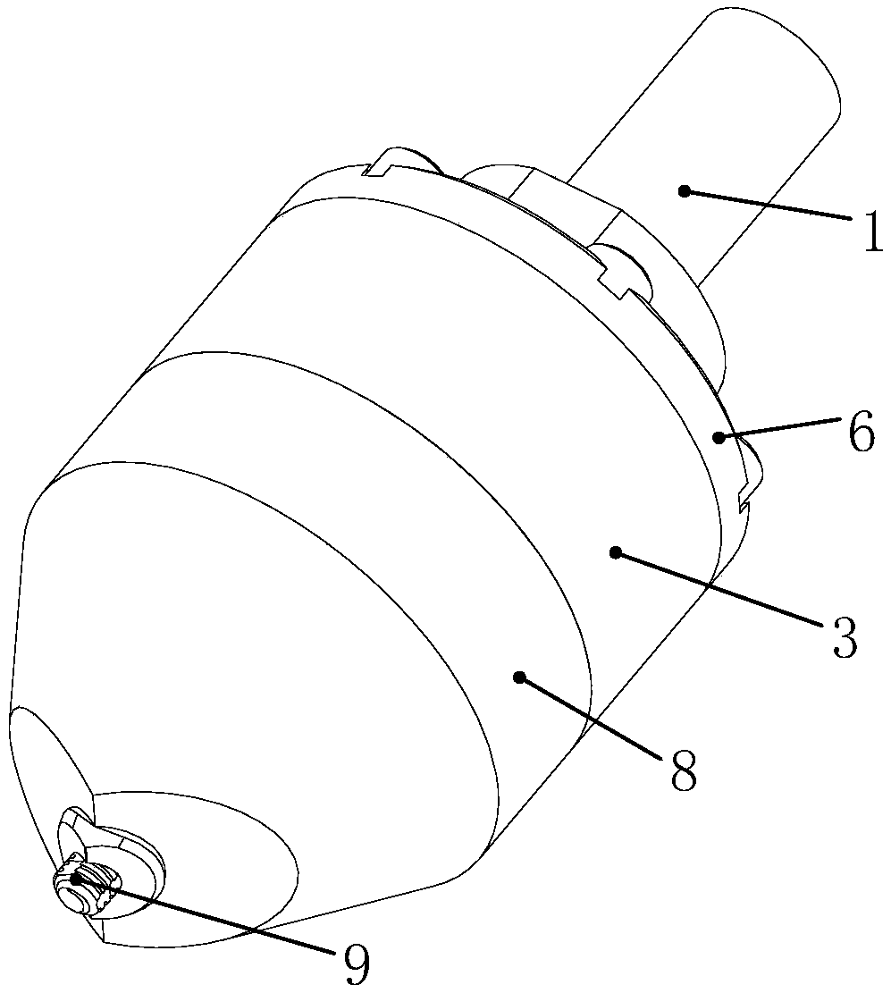
[0018] refer to Figure 1~3 As shown, the integral fillet weld friction stir welding tool involved in the present invention is mainly composed of a clamping end 1, a fastening screw 2, an adapter sleeve 3, a threaded sleeve 4, an end cover 6, a two-way thrust angular contact ball bearing 7, The static shaft shoulder 8 and the stirring needle 9 are composed. Among them, the stirring needle 9 is processed at the bottom of the clamping end 1; the inner ring of the two-way thrust angular contact ball bearing 7 has an interference fit with the clamping end 1, and the outer ring and the adapter sleeve 3 have a transition fit; the end cover 6 and the threaded sleeve 4 limit the clip The axial relative movement between the holding end and the ada...


PUM

PropertyMeasurementUnit
heightaaaaaaaaaa

Abstract

An integrated fillet weld stir friction welding tool is composed of a stationary shaft shoulder, a clamping end, a bidirectional thrust angular contact ball bearing, an adapter sleeve, a threaded sleeve and other parts. A stirring needle is processed at the bottom of the clamping end. An inner ring of the bidirectional thrust angular contact ball bearing is in interference fit with the clamping end, and an outer ring is in transition fit with the adapter sleeve. An end cover and the threaded sleeve are used for limiting the axial relative movement of the clamping end and the adapter sleeve, and the threaded sleeve and the clamping end are connected through threads. The stationary shaft shoulder and the adapter sleeve are connected through threads to ensure higher coaxiality between the stationary shaft shoulder and the stirring needle. According to the integrated filled weld stir friction welding tool and method, the axial displacement of the clamping end is applied to the stationary shaft shoulder through the bidirectional thrust angular contact ball bearing to generate the application of axial force in the welding process; and the rotating motion of the stirring needle is separated from the motion of the shaft shoulder, so that the effects of rotating the stirring needle and stopping the shaft shoulder are realized. According to the integrated filled weld stir friction welding tool and method, the friction stir welding of fillet welds can be carried out under the condition of not changing the structure of a main shaft of a machine tool, and the application range of friction stir welding equipment is expanded.

Description

technical field [0001] The invention belongs to the field of friction stir welding, in particular to an integral fillet weld friction stir welding tool and method. Background technique [0002] Friction stir welding technology has obvious advantages in connection strength, deformation and residual stress level, corrosion resistance, etc., and is widely used in aerospace, automobile, ship and other fields. The traditional stirring tool mainly consists of two parts, the shaft shoulder and the stirring needle, both of which rotate at the same time, and can weld a straight weld. However, in actual structures, there are a large number of non-planar or non-approximate planar joint forms such as fillet welds. It is difficult for traditional stirring tools to weld fillet welds due to the interference between the rotation of the shaft shoulder and the surface of the workpiece. [0003] In the prior art, the friction stir welding of fillet welds is realized mainly by adding process p...

Claims


Application Information

Patent Timeline
Patent Type & Authority Applications(China)
IPC IPC(8): B23K20/12B23K20/26
CPCB23K20/122B23K20/26
Inventor 董吉义徐奎尹玉环诸爱军封小松庄治华
Owner SHANGHAI AEROSPACE EQUIP MFG GENERAL FACTORY
Why Eureka
Try Eureka