Supercharge Your Innovation With Domain-Expert AI Agents!

Grid circuit for driving insulated gate bipolar transistor inverter

A technology for driving circuits and inverters, applied in circuits, logic circuits, semiconductor devices, etc., can solve problems such as noise generation, difficulty in IGBT inverters, and short circuits

Inactive Publication Date: 2005-06-01
LG IND SYST CO LTD
View PDF0 Cites 0 Cited by
  • Summary
  • Abstract
  • Description
  • Claims
  • Application Information

AI Technical Summary

Problems solved by technology

Therefore, noise is generated from the driving signal of the first IGBT 11 in a short time while the charge charged in the equivalent capacitance Cge between the gate and the emitter is discharged to the ground GND
[0021] As described above, according to the prior art IGBT inverter, when the noise generated from the driving signal of the first or second IGBT gate exceeds the threshold voltage, both the first and second IGBT are turned 'on' , so that the DC voltage and ground are shorted to each other
Therefore, a large current flows between them, which causes damage to each IGBT
[0022] Unfortunately, IGBT inverters according to the prior art have difficulties in minimizing the gate drive distance so that the noise does not exceed the threshold voltage, and in selecting the gate drive resistor and drive circuit, etc.

Method used


Image

  • Grid circuit for driving insulated gate bipolar transistor inverter
  • Grid circuit for driving insulated gate bipolar transistor inverter
  • Grid circuit for driving insulated gate bipolar transistor inverter

Examples


Embodiment Construction

[0037] Reference will now be made in detail to preferred embodiments of the invention, examples of which are illustrated in the accompanying drawings.

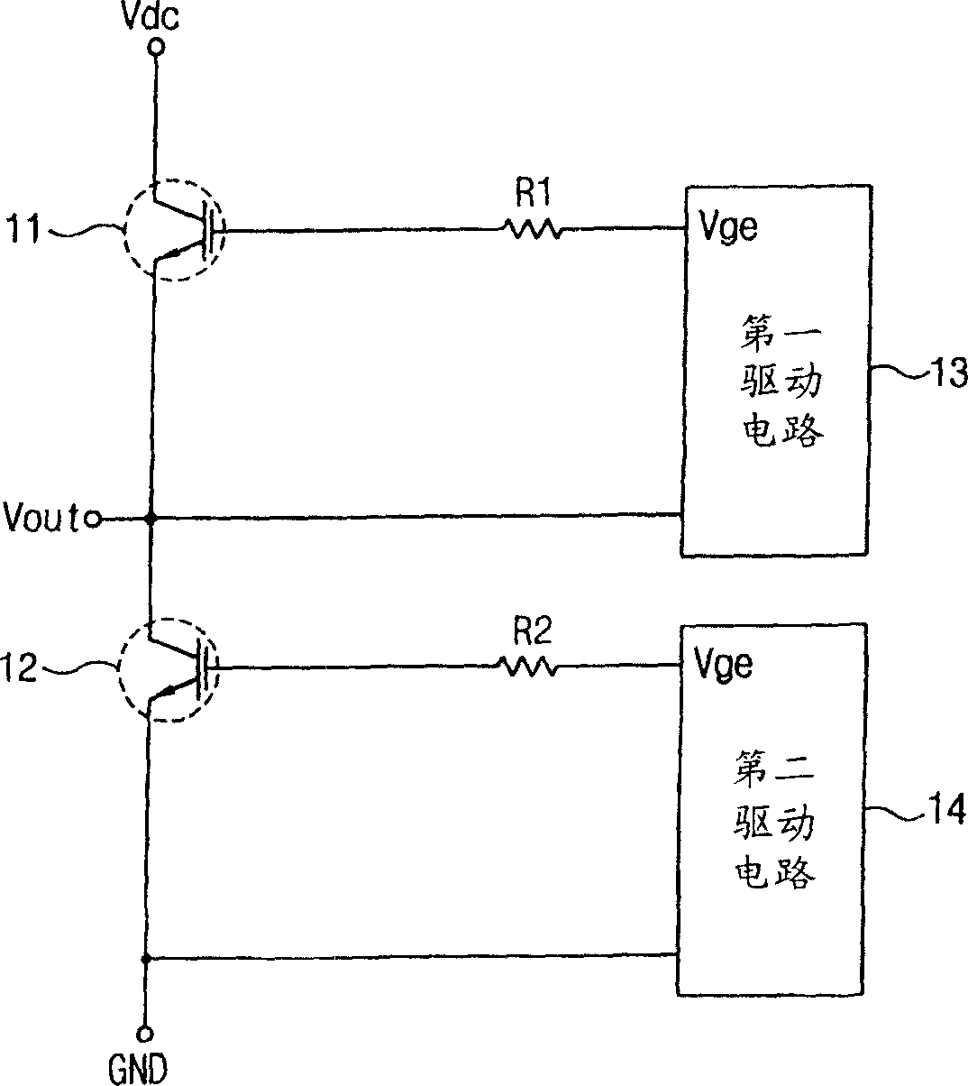
[0038] Figure 6 A circuit for driving the gate of an IGBT inverter according to the present invention is shown.

[0039] refer to Figure 6 , a circuit for driving the gate of an IGBT inverter according to the present invention includes: a first IGBT21, whose collector is connected to a DC power supply Vdc; a second IGBT22, whose collector is connected to the emitter of the first IGBT21, wherein , an output signal is output from the connection point between the collector of the second IGBT22 and the emitter of the first IGBT21, and the emitter of the second IGBT22 is connected to the ground GND; the first and second drive circuits 23 and 24, respectively, through The first and second gate resistors Rg21 and Rg22 supply DC drive voltages Vge and Vge to the gates and emitters of the first and second IGBTs 21 and 22; and the f...


PUM


Abstract

This paper discloses a circuit for driving the gate of an IGBT (Insulated Gate Bipolar Transistor) inverter. The circuit of the present invention comprises: a first IGBT, whose collector is connected to a DC voltage source; a second IGBT, whose collector is connected to the emitter of the first IGBT, wherein, from the collector of the second IGBT to the emitter of the first IGBT The connection point between the poles outputs an output signal, and the emitter of the second IGBT is connected to the ground; the first and second drive circuits are used to provide a DC drive voltage through the first and second gate resistors, respectively. to the gates and emitters of the first and IGBTs; the first and second noise blocking circuits are respectively connected between the gate-emitters of the first and second IGBTs and the first and second drive circuits, through The equivalent capacitance between the gate-emitters of the first and second IGBTs discharges the noise to block the noise. Therefore, the present invention can solve problems such as selection of a driving circuit, selection of a burnout driving resistance, and limitation of a gate driving distance. Also, the present invention can improve the reliability of the circuit.

Description

technical field [0001] The present invention relates to a circuit for driving the gate (gate) of an insulated gate bipolar transistor (insulated gate bipolar transistor, hereinafter abbreviated as IGBT) inverter, more specifically, relates to a single IGBT inverter A power gate drive circuit capable of driving the gate over long distances by eliminating noise generated when the gate is driven over long distances. Background technique [0002] figure 1 Indicates the equivalent circuit of a general-purpose IGBT device. In the single-supply driving method, a positive voltage or zero voltage is applied to the IGBT inverter. However, in the dual power supply driving method, positive voltage or zero voltage, or negative voltage is applied to the IGBT device. [0003] In the single power supply driving method, when a DC voltage is applied across the gate and the emitter, the collector and the emitter are electrically connected to each other. When zero voltage is applied between...

Claims


Application Information

Patent Timeline
Patent Type & Authority Patents(China)
IPC IPC(8): H02M1/00H02M1/08H03B1/00H03K3/00H03K17/08H03K17/16H03K17/56H03K17/567H03K17/687H03K19/00
CPCH03K17/168H01L29/70
Inventor 金敏极
Owner LG IND SYST CO LTD
Features
  • R&D
  • Intellectual Property
  • Life Sciences
  • Materials
  • Tech Scout
  • Unparalleled Data Quality
  • Higher Quality Content
  • 60% Fewer Hallucinations
Learn More