
Flat filter and filter system

A filter and plane technology, applied in waveguide-type devices, resonators, superconducting/high-conducting conductors, etc., can solve the problems of impossible realization, edge characteristics and corrugation deterioration, and achieve improved edge characteristics and elimination of corrugations. Effect

Inactive Publication Date: 2005-07-13
KK TOSHIBA
View PDF1 Cites 0 Cited by
  • Summary
  • Abstract
  • Description
  • Claims
  • Application Information

AI Technical Summary

Problems solved by technology

However, when this technique is applied to tune filter characteristics, only a uniform magnetic field can be applied to the corresponding resonant elements, and between the resonant elements or to the input / output section, the aforementioned (1) necessary for tuning the filter passband A separate and independent adjustment to (3) is therefore not possible, and the problem is that the change of the passband deteriorates the fringe characteristics and the ripple

Method used


Image

  • Flat filter and filter system
  • Flat filter and filter system
  • Flat filter and filter system

Examples


Embodiment Construction

[0031] Hereinafter, the planar filter of the present invention will be described in detail with reference to the accompanying drawings.

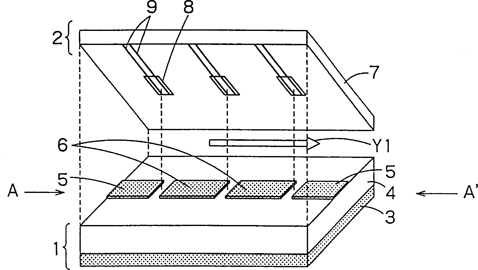
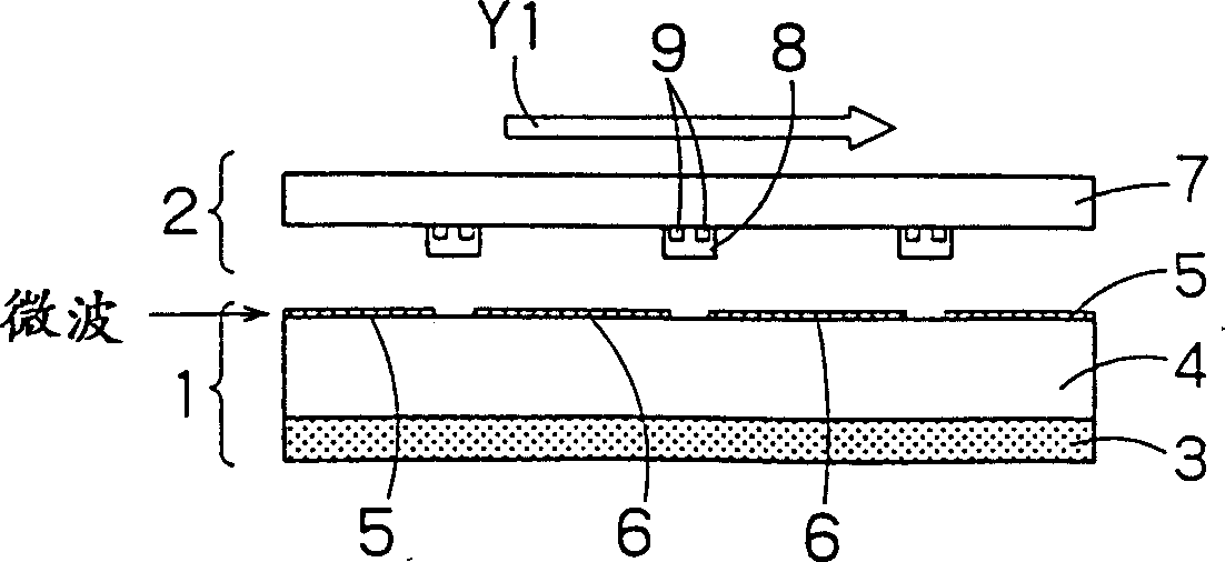
[0032] figure 1 shows a structural view of the first embodiment of the planar filter according to the present invention, and figure 2 for figure 1 Sectional view in direction A-A.

[0033] Such as figure 2 As shown, the planar filter of this embodiment is constructed in such a way that a planar filter component 1 is placed opposite to a similar planar tuning component 2 via a predetermined gap.

[0034] figure 1 shows the state before the filter part 1 is arranged to the opposite side of the tuning part 2, and figure 1 The dotted line at shows the vertical overlap position when the filter component is placed opposite the tuning component.

[0035] figure 1 The filter part 1 is a bandpass filter of a microstrip line structure, wherein a pair of input / output portions 5 formed of a superconductor, and similarly a plurality of resonant ...


PUM


Abstract

The present invention discloses a planar filter comprising: a filter part having a plurality of resonant elements formed of superconductor thin films and input / output placed on both sides of said resonant elements via gaps on a dielectric substrate part; and a tuning part formed of a magnetic material, said tuning part being placed opposite to said filter part through a predetermined gap, and a DC magnetic field is applied thereto. The tuning section includes a dielectric constant adjustment section that adjusts an effective dielectric constant of at least one of a gap edge between the resonance elements and a gap edge between the input / output portion and the resonance element.

Description

[0001] This application is related to the subject matter disclosed in Japanese Patent Application No. H11-276626 filed in Japan on September 29, 1999, which claims priority under the Paris Convention, and is incorporated herein by reference. technical field [0002] The present invention relates to a planar filter constituted by placing a filter part opposite to a tuning part, and in particular, the present invention relates to a technique of using a superconductor as a filter material for a communication device and the like. Background technique [0003] In a communication device that performs information communication by radio or cable, a filter for extracting only a desired frequency band is an important component. In order to realize effective use of frequencies and save energy, a filter with good attenuation characteristics and low insertion loss is required. [0004] To meet this need, a resonant element with a high Q value is an essential component of a filter. As a ...

Claims


Application Information

Patent Timeline
Patent Type & Authority Patents(China)
IPC IPC(8): H01P1/203
CPCH01P1/20363Y10S505/70Y10S505/866Y10S505/701H01P1/203
Inventor 寺岛喜昭福家浩之加屋野博幸芳野久士
Owner KK TOSHIBA
Learn More