Liquid control valve

A liquid control and valve casing technology, applied in the direction of fluid pressure control, fluid pressure control without auxiliary power, non-electric variable control, etc., can solve the problem that the valve cannot be closed

Inactive Publication Date: 2005-10-19
NOK CORP +1
View PDF1 Cites 0 Cited by
  • Summary
  • Abstract
  • Description
  • Claims
  • Application Information

AI Technical Summary

Problems solved by technology

[0002] At present, as a liquid control valve with both the function of automatically adjusting the pressure on the outflow side and the function of blocking water, the valve disclosed in Japanese Patent Publication No. 8-7456 is known. However, this prior art is to open the valve under normal conditions, Normally open valve unit that closes the valve on demand
Therefore, the problem is that it cannot be used directly as a normally closed toilet flushing valve that normally closes the valve and opens as needed, contrary to the normally open valve described above.

Method used


Image

  • Liquid control valve
  • Liquid control valve
  • Liquid control valve

Examples


Embodiment Construction

[0022] Hereinafter, embodiments of the present invention will be described based on the drawings.

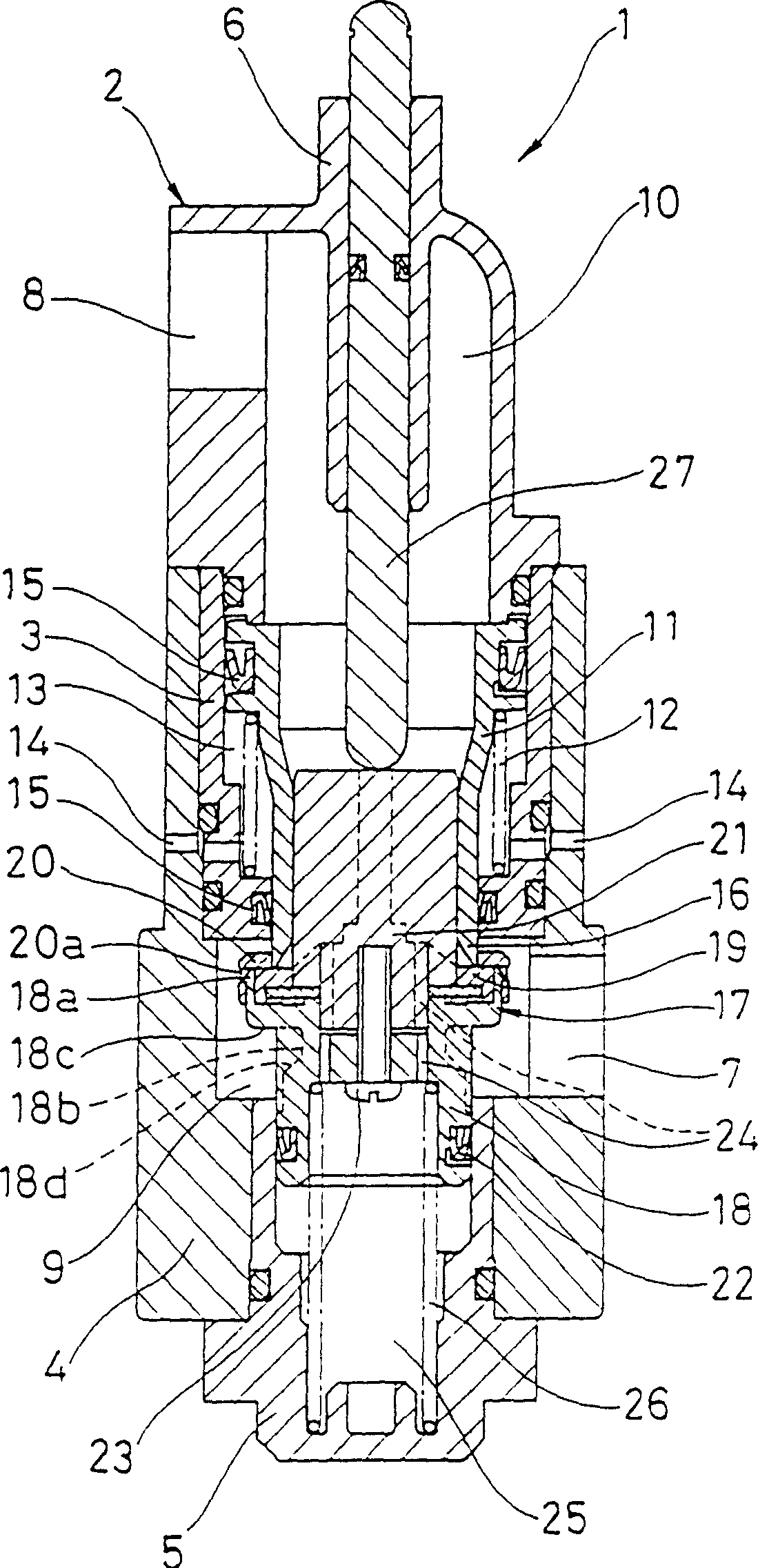
[0023] figure 1 A cross-section of the liquid control valve 1 according to the embodiment of the present invention is shown. The structure of the control valve 1 is as follows.

[0024] That is, first, the valve housing main body 3, the main body 4, the cover 5, and the end cover 6 are combined so as not to leak water. These parts form the valve housing 2, and the valve housing 2 is provided with a liquid inflow port 7 and an outflow port 8. . The inflow port 7 is provided on the side surface of the main body 4 and communicates with the inflow side pressure chamber 9 inside the main body 4, and the outflow port 8 is provided on the side surface of the end cover 6 and communicates with the outflow side pressure chamber 10 inside the end cover 6.

[0025] On the inner peripheral side of the valve housing main body 3 of the valve housing 2, the pressure regulating piston 11 is arrang...


PUM


Abstract

In order to achieve an object to provide a liquid control valve of normally close valve type which has both of an outflow side pressure automatic regulating function and a water stop function, the liquid control valve has a pressure regulating piston which moves within a housing for finding a balance point between an outflow side pressure and a spring force of a pressure regulating spring placed so as to resist the outflow side pressure; a movable valve seat which is provided in the pressure regulating piston and moves together with the pressure regulating piston; and a valve body which sits on the valve seat so as to close the valve in accordance with a valve closing force generated by an inflow side pressure and a spring force of a water stop spring, and moves apart from the valve seat so as to open the valve at the time when an external valve opening force larger than the valve closing force is applied, whereby the outflow side pressure automatic regulating function is achieved in accordance with movement of the pressure regulating piston, and the water stop function is achieved in accordance with the valve close.

Description

Technical field [0001] The invention relates to a liquid control valve for controlling the flow of liquid, in particular to a liquid control valve that has both the function of automatically adjusting the pressure on the outflow side and the function of water blocking. The liquid control valve is used as, for example, a toilet flushing valve for supplying flushing water to a toilet. Background technique [0002] At present, as a liquid control valve that has both the function of automatically adjusting the pressure on the outflow side and the water barrier function, there is known a valve disclosed in the Japanese Kokai Publication No. 8-7456. However, this prior art technique is to open the valve under normal conditions. Normally open valve type valve device that closes the valve as required. Therefore, the problem is that it cannot be directly used as a normally closed toilet flushing valve which is the opposite of the aforementioned normally open valve, which closes the valve ...

Claims


Application Information

Patent Timeline
Patent Type & Authority Patents(China)
IPC IPC(8): F16K17/30G05D16/10
CPCG05D16/106G05D16/103Y10T137/7782Y10T137/7798Y10T137/7808Y10T137/7834G05D16/10
Inventor 山下松喜
Owner NOK CORP
Why Eureka
Try Eureka