Link pin type movable floor boards

A raised floor, bayonet-type technology, applied in the field of building decoration materials, can solve the problems of inability to renovate pipelines, inconvenient disassembly, complicated floor manufacturing process, etc., and achieve the effects of flexible use of manufacturing costs, convenient installation and disassembly, and easy installation.

Inactive Publication Date: 2005-11-09
JIANGSU EAST CHINA COMP ROOM GROUPS
View PDF0 Cites 0 Cited by
  • Summary
  • Abstract
  • Description
  • Claims
  • Application Information

AI Technical Summary

Problems solved by technology

The biggest defect of this kind of floor is that once it is installed, it cannot be easily disassembled; in addition, with the continuous increase of household appliances, many pipelines are routed from the ground, and if the above-mentioned floor is laid, the pipeline can only be buried. That is, before laying the floor, cut grooves on the concrete floor to place the pipeline, which not only wastes man-hours but also destroys the strength of the ground. After the floor is laid, when the indoor household appliances and furniture increase or the position changes, the pipeline cannot be easily modified
As another example, modern office buildings often use all-steel raised floors or composite raised floors (such as figure 2 ) to decorate the floor. Because of the overhead space, the pipeline does not need to be pre-buried, and it can be easily assembled and disassembled. However, due to the complicated manufacturing process of the floor, the cost is high, the price is expensive, and the installation process is relatively complicated, which requires professional installation. team, not suitable for home and general office use

Method used


Image

  • Link pin type movable floor boards
  • Link pin type movable floor boards
  • Link pin type movable floor boards

Examples


Embodiment 1

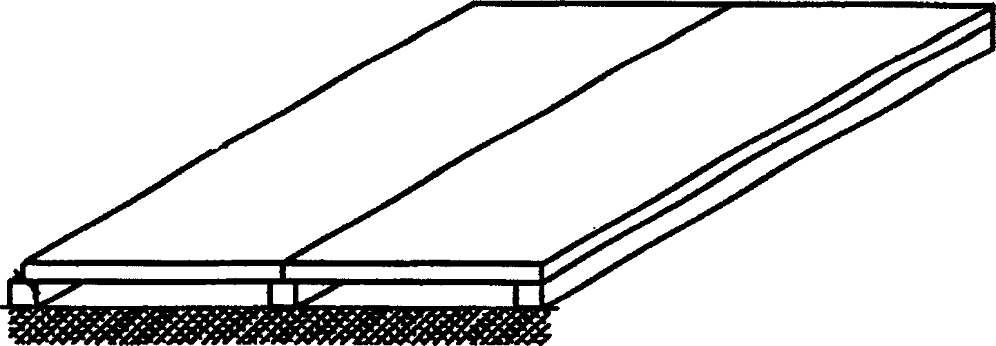
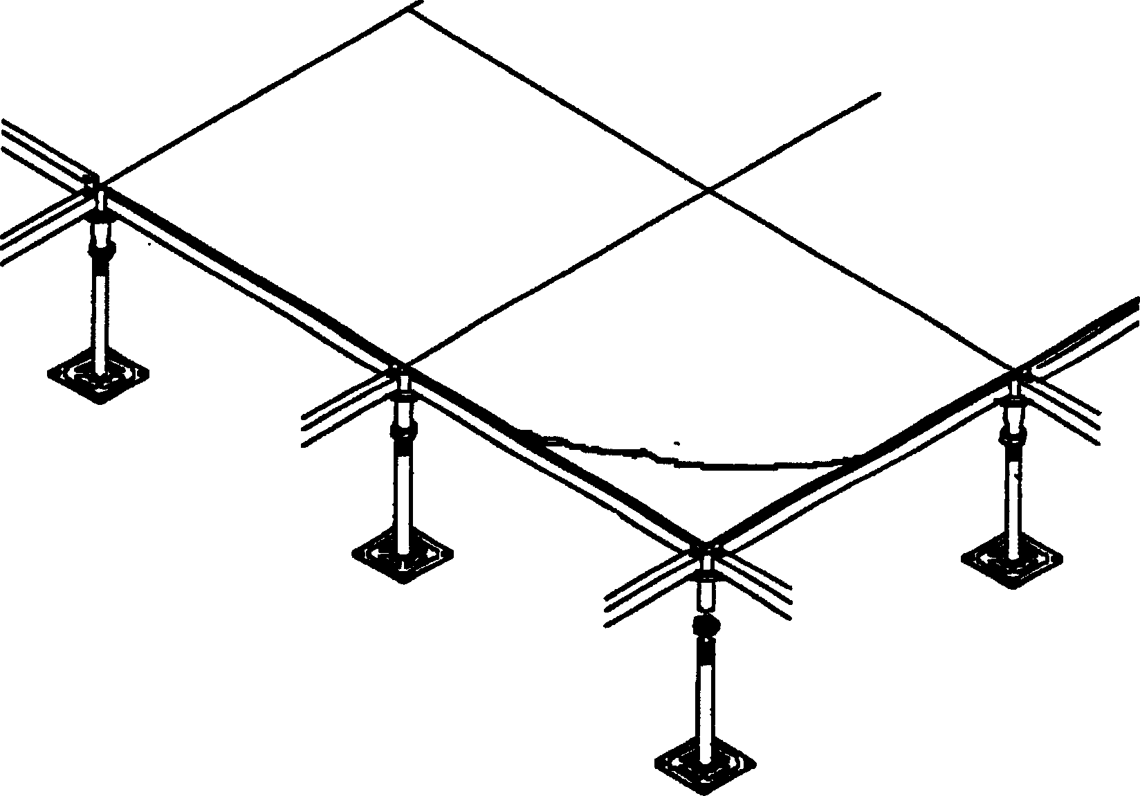
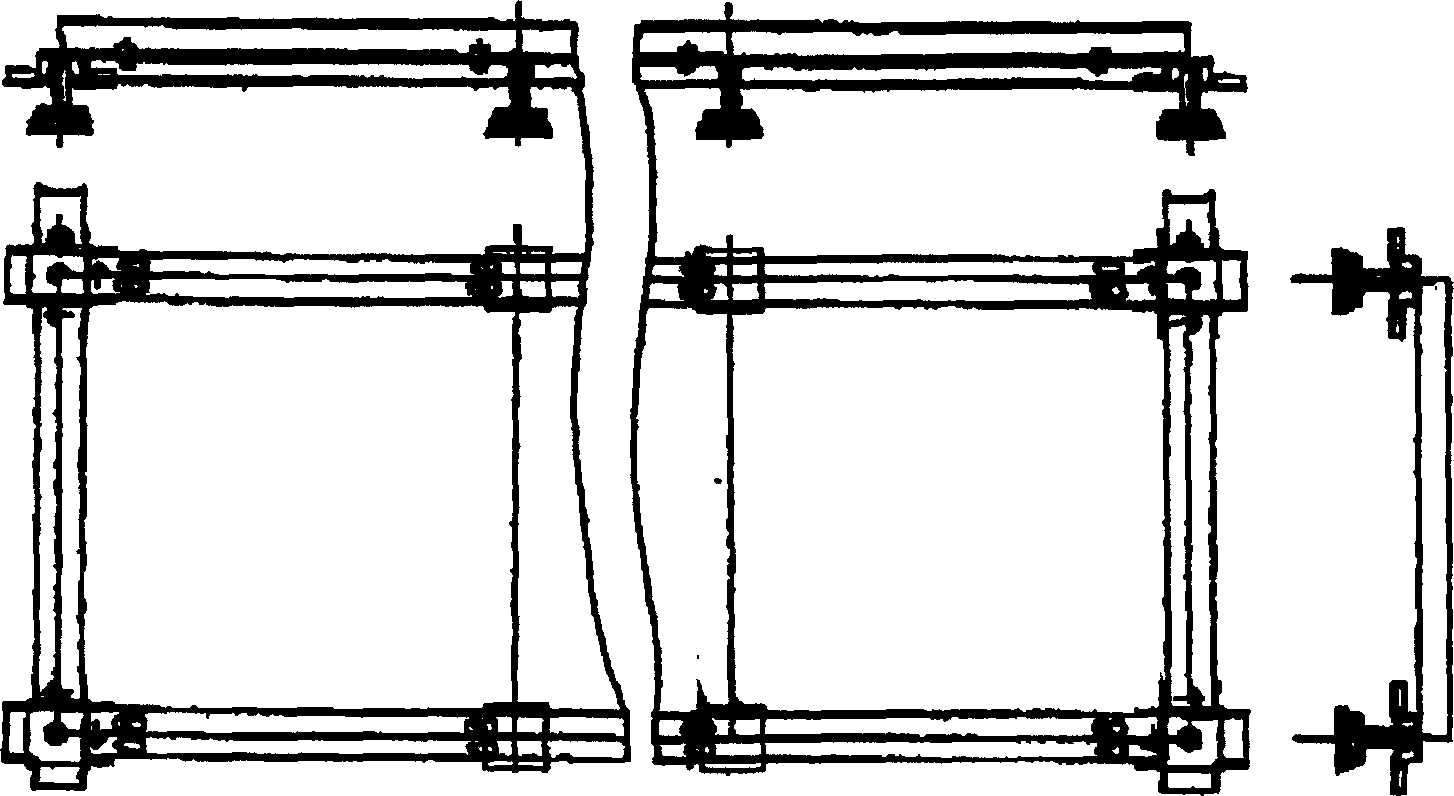
[0033] Embodiment 1: As shown in floor 5-7. 1 is the cross section Shaped tongue-and-groove composite board, one side is a floor groove 11, the other side is a floor beam 12, the beam 2, the support seat 5, and the screw rod 3 fixed in the swing groove 51 arranged on the support seat 5 constitute the floor 1 The supporting device and the setting of the swing groove 51 can play a shockproof and buffering role. The crossbeam 2 is provided with a threaded sleeve 4 threadedly connected with the screw rod 3. The floor 1 is arranged on the crossbeam 2. The formed buffer pad 10 has a bayonet pin 6 fixed under the floor 1, the front part of the bayonet pin 6 is a bayonet head 61, the middle part of the bayonet 6 is a bayonet neck 62, and the radial dimension of the bayonet head 61 is larger than the bayonet pin. The neck 62 is provided with a slot 7 corresponding to the bayonet pin 6 on the crossbeam 2. The bayonet 7 has a bayonet hole 71 slightly larger than the bayonet head 61. Th...

Embodiment 2

[0035] Embodiment two: if Figure 8 and Figure 9 . The difference from Embodiment 1 is that the floor 1 adopts The composite floor of cross-section; the slot hole is the slot, and the slot 7 of the crossbeam 2 is provided with two relative springs 8 in the shape of "eight" that can hold the pin 6.

[0036] During installation, it is only necessary to align the bayonet pin 6 of the floor 1 with the bayonet groove 7, and press down with a little force, and the bayonet pin 6 is promptly blocked by the spring leaf 8.

Embodiment 3

[0037] Embodiment three: as Figure 10 and Figure 11 . The difference with Embodiment 2 is that the floor 1 adopts Composite floor with shaped cross-section; two spring seats 9 with springs 91 are oppositely arranged below the draw-in groove 7 of the beam 2, and a steel ball 92 is connected to the front ends of the springs 91 of the two opposite spring seats 9, and a steel ball 92 is connected to the opposite two steel balls. The ball 92 can block the bayonet 6 inserted into the bay 7 according to the spring.

[0038] Similar to the installation of Embodiment 2, just align the bayonet pin with the bayonet groove and press down, the bayonet pin is locked by the two opposite steel balls, and the floor and the beam are fitted together.


PUM


Abstract

A link pin-type movable floor is composed of floor boards and supporting units consisting of supporting frame, stand and supporting rod between them. Said floor boards are arranged on the supporting frames, which are linked by link pins. Its advantages are low cost, and easy assembly and disassembly.

Description

technical field [0001] The invention relates to the field of building decoration materials, in particular to a raised floor suitable for households, office buildings, stadiums and other occasions. Background technique [0002] Modern families often use wooden floors to decorate the ground, such as figure 1 , the floor is nailed to the strips; the strips are nailed to the ground. The biggest defect of this kind of floor is that once it is installed, it cannot be easily disassembled; in addition, with the continuous increase of household appliances, many pipelines are routed from the ground, and if the above-mentioned floor is laid, the pipeline can only be buried. That is, before laying the floor, dig grooves on the concrete floor to place the pipeline, which not only wastes man-hours but also destroys the strength of the ground. After the floor is laid, when the indoor household appliances and furniture increase or the position changes, the pipeline cannot be easily modifie...

Claims


Application Information

Patent Timeline
Patent Type & Authority Patents(China)
IPC IPC(8): E04F15/00
Inventor 孙世度张建华
Owner JIANGSU EAST CHINA COMP ROOM GROUPS
Why Eureka
Try Eureka