Magnetically sucked movable floor

A raised floor, magnetic suction technology, applied in the field of building decoration materials, can solve the problems of inability to renovate the pipeline, inconvenient disassembly, complicated floor manufacturing process, etc., and achieve the effect of flexible use of manufacturing cost, easy installation, and convenient installation and disassembly.

Inactive Publication Date: 2005-11-09
JIANGSU EAST CHINA COMP ROOM GROUPS
View PDF0 Cites 0 Cited by
  • Summary
  • Abstract
  • Description
  • Claims
  • Application Information

AI Technical Summary

Problems solved by technology

The biggest defect of this kind of floor is that once it is installed, it cannot be easily disassembled; in addition, with the continuous increase of household appliances, many pipelines are routed from the ground, and if the above-mentioned floor is laid, the pipeline can only be buried. That is, before laying the floor, cut grooves on the concrete floor to place the pipeline, which not only wastes man-hours but also destroys the strength of the ground. After the floor is laid, when the indoor household appliances and furniture increase or the position changes, the pipeline cannot be easily modified
As another example, modern office buildings often use all-steel raised floors or composite raised floors (such as figure 2 ) to decorate the floor. Because of the overhead space, the pipeline does not need to be pre-buried, and it can be easily assembled and disassembled. However, due to the complicated manufacturing process of the floor, the cost is high, the price is expensive, and the installation process is relatively complicated, which requires professional installation. team, not suitable for home and general office use

Method used


Image

  • Magnetically sucked movable floor
  • Magnetically sucked movable floor
  • Magnetically sucked movable floor

Examples


Embodiment 1

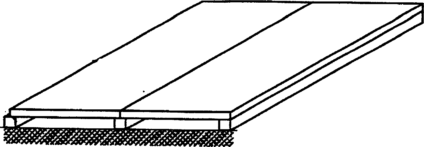
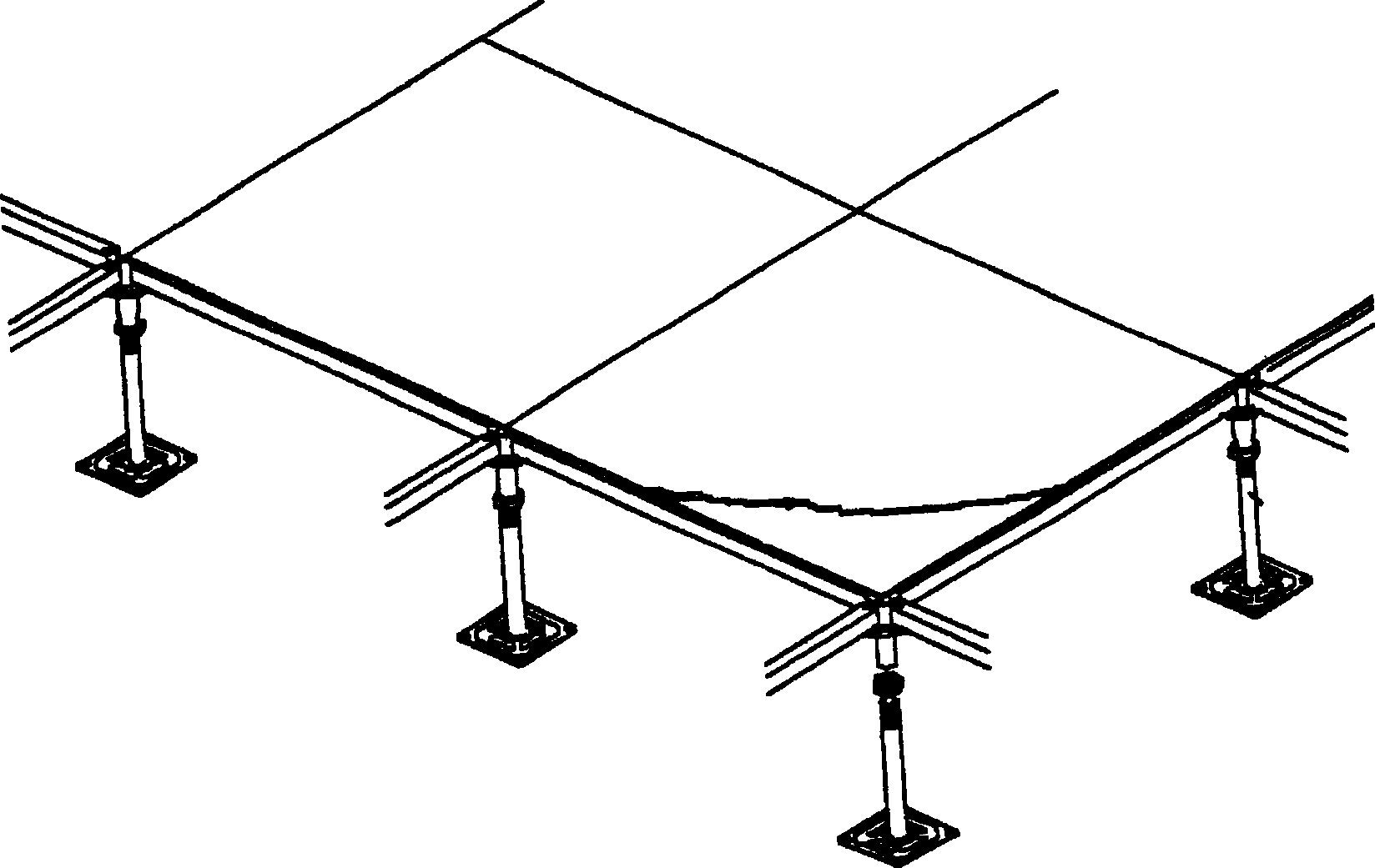
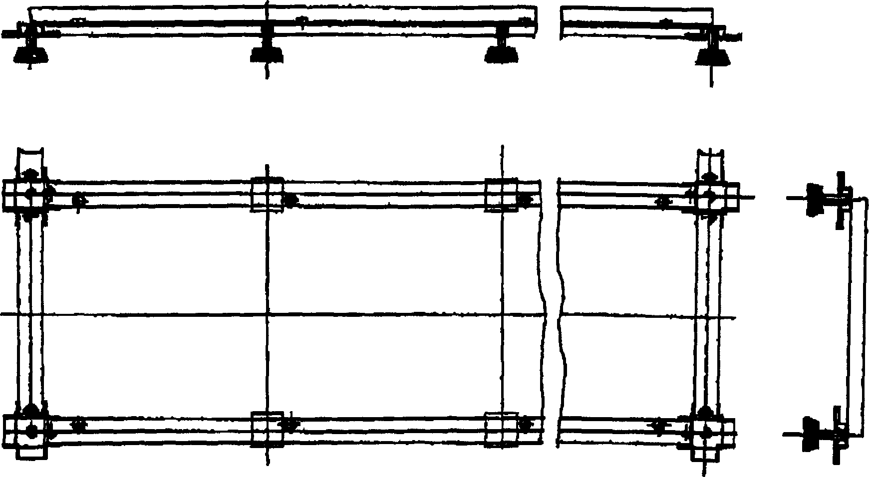
[0033] Embodiment one: if Figure 5-7 . 1 is the cross section of Shaped tongue-and-groove composite board, one side is the floor groove 11, the other side is the floor beam 12, the steel beam 2, the support seat 5, the screw rod 3 fixed in the swing groove 51 arranged on the support seat 5 Constituting the supporting device of the floor 1, the setting of the swing groove 51 can play a shockproof and buffering role. The crossbeam 2 is provided with a threaded sleeve 4 threadedly connected with the screw rod 3, the floor 1 is arranged on the crossbeam 2, and the floor 1 and the crossbeam 2 are provided with a A buffer pad 10 made of rubber, a magnet 6 made of a permanent magnet is fixedly embedded in a slot 7 under the floor 1 .

[0034] During actual installation, the support base 5 can be glued to the ground as required, the floor is placed on the beam, and the floor and the beam can be firmly connected together by the magnetic force between the magnet 6 and the beam. Sim...

Embodiment 2

[0035] Embodiment two: if Figure 8 and Figure 9 . The difference from Embodiment 1 is that the floor 1 adopts Shaped cross-section composite floor; and the magnet 6 is fixed below the floor 1 by wood screws 8.

Embodiment 3

[0036] Embodiment three: as Figure 10-12 . The difference with Embodiment 2 is that the floor 1 adopts A composite floor with a cross-section; the magnet 6 is a magnetic powder strip, which is composed of an adhesive tape layer 61 and a magnetic powder layer 62 coated on it. The other side of the adhesive tape layer 61 is glued under the floor 1, and then the floor is placed on the beam 2. The magnetic attraction force of the magnetic powder layer 62 firmly absorbs the floor and the beam.


PUM


Abstract

A magnetically sucked movable floor is composed of floor, supporter consisting of support fram, base and support rod, and the magnetic sucker between floor and supporter. Its advantage is high stability.

Description

technical field [0001] The invention relates to the field of building decoration materials, in particular to a raised floor suitable for households, office buildings, stadiums and other occasions. Background technique [0002] Modern families often use wooden floors to decorate the ground, such as figure 1 , the floor is nailed to the strips; the strips are nailed to the ground. The biggest defect of this kind of floor is that once it is installed, it cannot be easily disassembled; in addition, with the continuous increase of household appliances, many pipelines are routed from the ground, and if the above-mentioned floor is laid, the pipeline can only be buried. That is, before laying the floor, dig grooves on the concrete floor to place the pipeline, which not only wastes man-hours but also destroys the strength of the ground. After the floor is laid, when the indoor household appliances and furniture increase or the position changes, the pipeline cannot be easily modifie...

Claims


Application Information

Patent Timeline
Patent Type & Authority Patents(China)
IPC IPC(8): E04F15/00
Inventor 孙世度张建华
Owner JIANGSU EAST CHINA COMP ROOM GROUPS
Why Eureka
Try Eureka