Fume cleaning regulating method and apparatus by indirect evaporating liquid utilizing the residual heat of fume

A flue gas waste heat and flue gas purification technology, applied in chemical instruments and methods, separation methods, solid separation, etc., can solve the problems of large heat exchanger equipment, insufficient smoke and dust contact, and large demand for cooling medium, and reduce Emission of inhalable particulate matter, long trouble-free operation time, and the effect of reducing flue gas flow under operating conditions

Inactive Publication Date: 2006-07-12
陶国龙
View PDF0 Cites 0 Cited by
  • Summary
  • Abstract
  • Description
  • Claims
  • Application Information

AI Technical Summary

Problems solved by technology

Its disadvantages are: a. What is injected into the flue gas is SO 3 , NH 3 , and other polluting gases, if there is no corresponding effective removal facility behind the electrostatic precipitator, it will be discharged along the chimney, causing new pollution to the environment; b, significantly increasing the acid dew point temperature of the flue gas, will locally cool down the follow-up equipment cause corrosion everywhere; c, high equipment investment and operating costs; d, high requirements for the control system, relatively complex
The disadvantages are: a. Large amount of solvent required and high operating costs; b. Insufficient contact between solution and dust, especially fine particles; c. Relatively complex system composition and control system, high equipment investment
But its disadvantages are: a. There must be a special spray humidification tower or a flue of sufficient length to meet the requirements of the droplet evaporation time; b. The atomized water droplets usually adopt the method of pressure atomization or two-phase flow gas-assisted atomization
Although the deficiencies of the third method are basically overcome, there are also certain disadvantages: a. The heat exchange intensity is relatively s

Method used


Image

  • Fume cleaning regulating method and apparatus by indirect evaporating liquid utilizing the residual heat of fume
  • Fume cleaning regulating method and apparatus by indirect evaporating liquid utilizing the residual heat of fume
  • Fume cleaning regulating method and apparatus by indirect evaporating liquid utilizing the residual heat of fume

Examples


Embodiment Construction

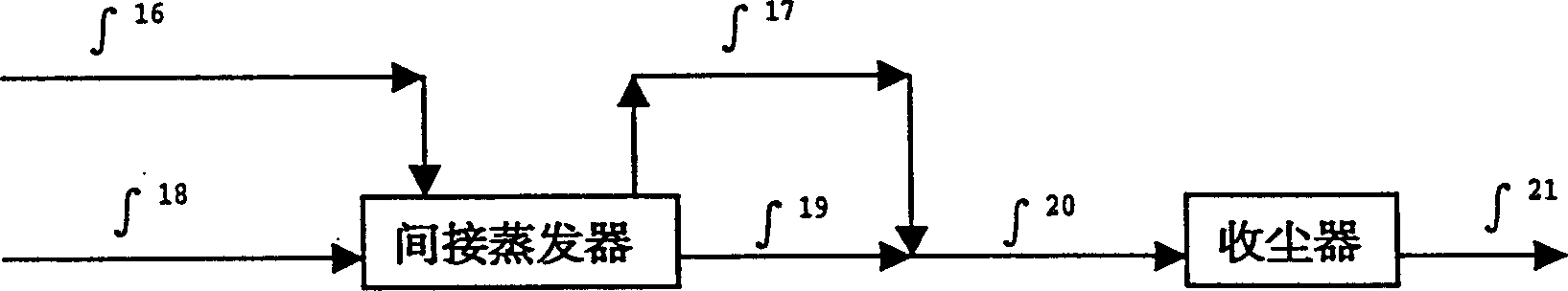
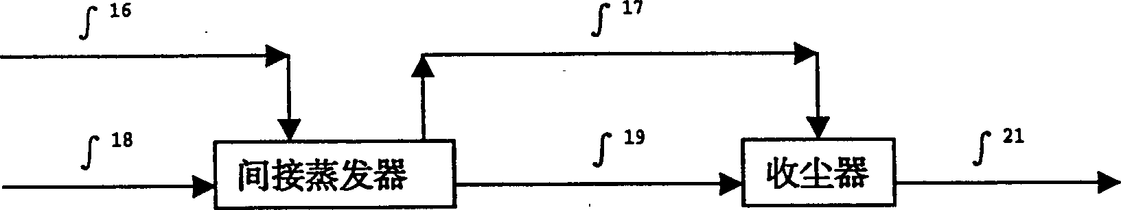
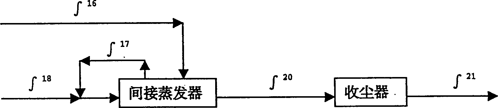
[0025] Such as Figure 1-4 As shown, a flue gas purification and tempering method that utilizes flue gas waste heat to indirectly evaporate liquid, the dust-laden hot flue gas 18 from the combustion source or heat utilization device flows through the heat source section 10 of the indirect evaporator, and passes through the heat source section 10 The heat conduction element group 5 that penetrates the heat source section 10 and the evaporation section container 1 and seals both absorbs heat from the hot dusty flue gas 18 flowing through the heat source section 10 and transfers it to the evaporation section 6, indirectly heats and evaporates at a certain liquid supply speed Supply the liquid 16 in the container 1 of the evaporation section. When the liquid 16 heats up and evaporates, it absorbs a large amount of latent heat of vaporization and the heat required for temperature rise from the dust-laden hot flue gas 18 through the heat conduction element group 5, so that the dust-l...


PUM


Abstract

A method of cleansing smokes by indirectly evaporating liquid through remaining heat of smoke and its device. The device comprises heat source, evaporating container, heat conductive member. Taking advantage of the remaining heat of smoke, liquid is evaporated by the heat conductive member. When the liquid is heated and evaporated, it greatly absorbs energy from warm smoke containing dust by the heat conductive member, the temperature of the smoke drops to an objective value. Steam from the liquid is mixed with smoke by a steam pipeline before a dust-collecting machine. In the manner, the smoke is cool, increase humidity, purified, which improve the purifying effect of the dust-collecting machine.

Description

technical field [0001] The invention relates to a method and device for conditioning and tempering dust-laden hot flue gas discharged from industries such as coal-fired power plants, building materials, metallurgy, and chemical industry, and specifically relates to the field of electric dust collection or filter bag dust collection, especially a method using Disclosed are a flue gas purification and tempering method and device for cooling and humidifying flue gas by indirectly evaporating liquid with waste heat of flue gas. Background technique [0002] With the increasingly stringent environmental emission standards, more and more original dust collectors cannot meet the requirements of smoke and dust emission standards, especially in order to reduce coal-fired SO 2 emissions, more and more coal-fired boilers are replaced by low-sulfur coal to meet the reduction of SO 2 requirements, while reducing the huge amount of SO 2 Payment of sewage charges. But what follows is th...

Claims


Application Information

Patent Timeline
IPC IPC(8): B03C3/014B01D53/32
Inventor 陶国龙
Owner 陶国龙
Why Eureka
Try Eureka