Double guide mechanism

A guide rail and duplex technology, applied to furniture parts, household appliances, drawers, etc.

Inactive Publication Date: 2006-11-01
KYOEI IND CO LTD
View PDF1 Cites 0 Cited by
  • Summary
  • Abstract
  • Description
  • Claims
  • Application Information

AI Technical Summary

Problems solved by technology

[0004] However, when pulling out in such a sequence, when the middle rail is stopped relative to the rail on the main body side, due to its reaction force, an impact force is generated to stop the rail on the side of the drawer being pulled out, which prevents the rail mechanism from being smooth. , a reason for moving quietly

Method used


Image

  • Double guide mechanism
  • Double guide mechanism
  • Double guide mechanism

Examples


Embodiment Construction

[0025] Hereinafter, a more detailed description will be given based on the embodiment examples shown in the accompanying drawings of the present invention.

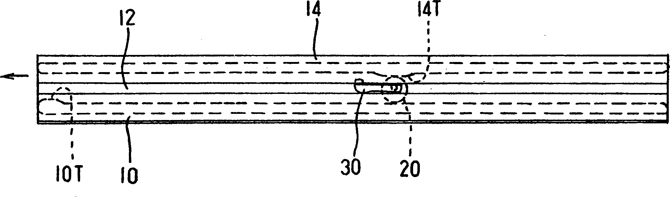
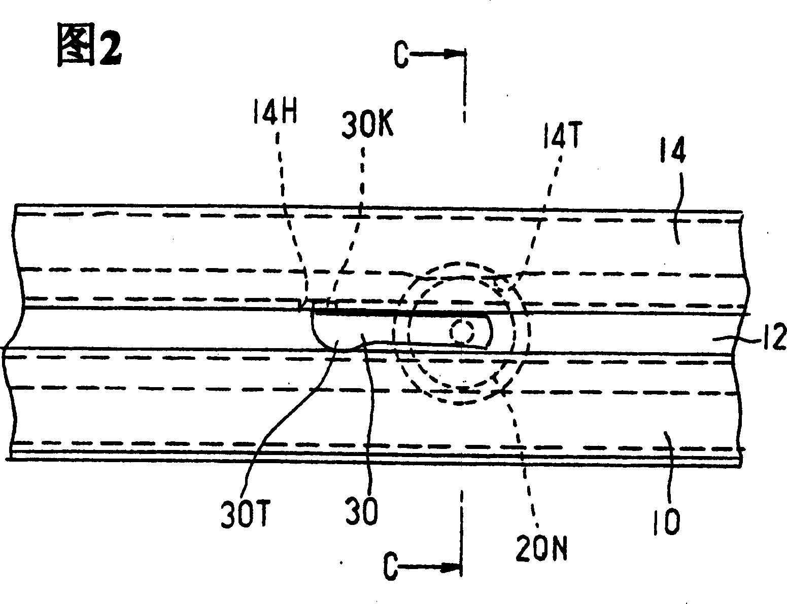
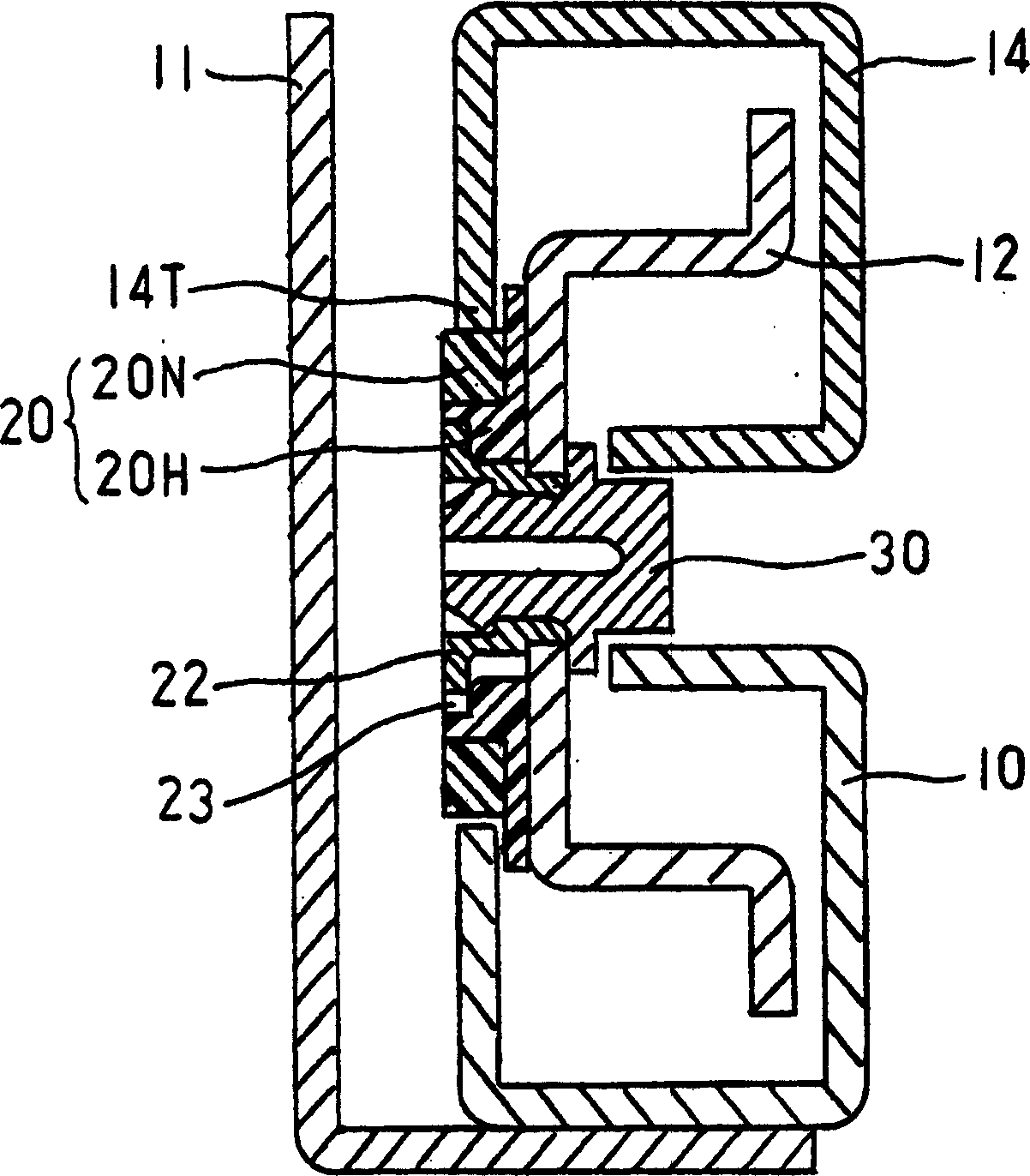
[0026] figure 1 It is a side view of the guide rail mechanism of the unillustrated cabinet drawer with the compound guide rail mechanism related to the present invention in the storage state, and Fig. 2 is an enlarged view of its main parts, image 3 It is an enlarged cross-sectional view according to the arrow line C-C in FIG. 2 . In the cross-section, on one end side (lower side) of the middle rail 12, a frame side rail 10 is provided. The rail is rectangular and surrounds the above-mentioned one end. One corner is open. It is provided by (a combination of) a plurality of rollers (combination) that are not shown in the figure and are provided in the front-rear direction as rotating bodies. In addition, the other end side (upper side) is provided with a drawer side rail 14, which is rectangular and surrounds the above-...


PUM


Abstract

The present invention provides a double guide-rail mechanism that can be operated in a smooth and quiet manner. A main body projection 10T is installed on a front section of a main body side rail 10. With an intermediate rail completely pulled out of the main body side rail, a roller 20 is rotatably installed at a position P2' of the intermediate corresponding to a predetermined distance &dgr; from a rear end position P1' of the main body projection. Connecting mechanisms 30, 14 are arranged whereby in the process when a drawer object is pulled out from a completely received condition to such an extent that the roller reaches the main body projection, and during the process that the rollers moves away from the main body projection to a completely received condition in the process of receiving the drawer object, the intermediate rail is moved with the drawer object side rail, otherwise they are separate.

Description

technical field [0001] The invention relates to a compound guide rail mechanism used for smoothly pulling out and re-storing pull-out bodies of office furniture such as cabinets or household furniture. A pull-out body generally refers to an object to be pulled out, including a drawer and a table to be pulled out. Background technique [0002] Some cabinets and other double guide rail mechanisms have: the drawer-side track installed on the drawer side, the main body-side track installed on the frame (main body) side, and the cylindrical (cylindrical) track between each track. A roller or spherical ball that can move relative to the middle track. For example, Patent Document 1 below discloses an example of such a structure. As in the description of this document, pull out in the order of Figures 6 (a), (b2), and (c) of the document, and store in the reverse order, which can reduce the load on the specified rotating body . In other words, when pulling out, the rail on the s...

Claims


Application Information

Patent Timeline
Patent Type & Authority Patents(China)
IPC IPC(8): A47B88/08A47B88/04A47B88/49A47B88/493
Inventor 李丁
Owner KYOEI IND CO LTD
Why Eureka
Try Eureka