Surveillance System and Method for Detecting Forbidden Movement along a Predetermined Path

a surveillance system and path technology, applied in the field of surveillance systems, can solve problems such as pursuing violators, monetary damages and/or physical injuries, and crashes that, in many cases, are fatal,

Inactive Publication Date: 2009-02-12
PLANUM VISION
View PDF10 Cites 44 Cited by
  • Summary
  • Abstract
  • Description
  • Claims
  • Application Information

AI Technical Summary

Benefits of technology

[0109]f. transferring data from the camera to the control station.

Problems solved by technology

There are many kinds of activities or movements that are generally forbidden, each of which may take place at a different location along a path and may violate one or more laws.
If left undetected, certain activities may directly or indirectly cause harm, resulting in monetary damages and / or physical injury.
For instance, it is widely known that traffic violations, including improper lane changes, passing on the wrong side or without sufficient distance, following too closely (tailgating), failing to obey traffic signals, changing speed suddenly, traveling over the speed limit, turning from the wrong lane, etc. may result in crashes that, in many cases, are fatal.
Additionally if the officer notices any other type of traffic violation occurring, he may pursue the violator.
However, since the officer is situated at a fixed location, he is only capable of through his fixed field of view.
In all prior art surveillance systems, the camera, whether fixed or mobile, is only capable of detecting activity along a fixed plane and at a fixed distance from the road.
For cases where a vehicle may be tailgating, the detection of the license plate is difficult due to the angle of the camera with respect to the vehicle.
Some problems associated with surveillance airplanes include mishaps that occur especially during landing and takeoff.
When flying with reduced speed, a loss of aerial stability occurs, and as such, these airplanes are extremely sensitive to aerodynamic changes and disturbances (e.g. changes in wind speed or direction).
However, when the criminal is out of sight of the police officer, the activity may be performed undetected.
Boats may be transporting illegal products, and / or they may not be sailing according to the rules of the particular canal or waterway.
In cases where the canal extends over a long distance, the coastguard may not have the capability to keep the entire length of the canal under surveillance.
Such activities may include vandalism by puncturing the pipe, or in order to illegally siphon off a quantity of the transported material.
It is well known that even a physical barrier, such as a wall or a barbed wire fence, is often not enough to prevent intruders from entering a restricted area.
However, this type of patrolling system is generally not fully effective, since the intruder must merely wait until he is out of view of the patroller, before attempting entry to the area.
Additionally, land vehicles may find it difficult to traverse certain terrain, thereby hindering their patrolling capabilities.
However, an intruder may bypass the camera in a similar manner as with land vehicles, by remaining undetected until he is not in the camera's field of view.
An additional problem associated with prior art surveillance systems, especially those situated within a restricted area, is that when the camera is stationary and positioned below the height of the fence, the outer, unrestricted area, is partially obstructed by the fence itself.
Moreover, when the camera travels along the perimeter of the fence, when reaching certain speeds, and depending on the size of the openings in the fence, the camera's view of the unrestricted area may be essentially completely obstructed by the fence.
Even if the camera is situated above the fence so as not to be obstructed by the fence, by mounting the camera within the restricted area, undesirable dead space outside of the area results, where a potential intruder may hide without being detected.
However, an unmanned remotely controlled airplane, or, UAV (Unmanned Aerial Vehicle) typically comprises additional, costly and heavy control systems, and are typically not limited to merely traveling around the boundary of a predetermined area.
Additionally, since UAV's are limited in the amount of time that can be spent in flight, they must spend valuable time and fuel traveling to and from the landing field, which is generally located at a distance from the area requiring surveillance.
Other problems associated with surveillance airplanes include mishaps that occur especially during landing and takeoff, as described herein above.

Method used


Image

  • Surveillance System and Method for Detecting Forbidden Movement along a Predetermined Path
  • Surveillance System and Method for Detecting Forbidden Movement along a Predetermined Path
  • Surveillance System and Method for Detecting Forbidden Movement along a Predetermined Path

Examples


first embodiment

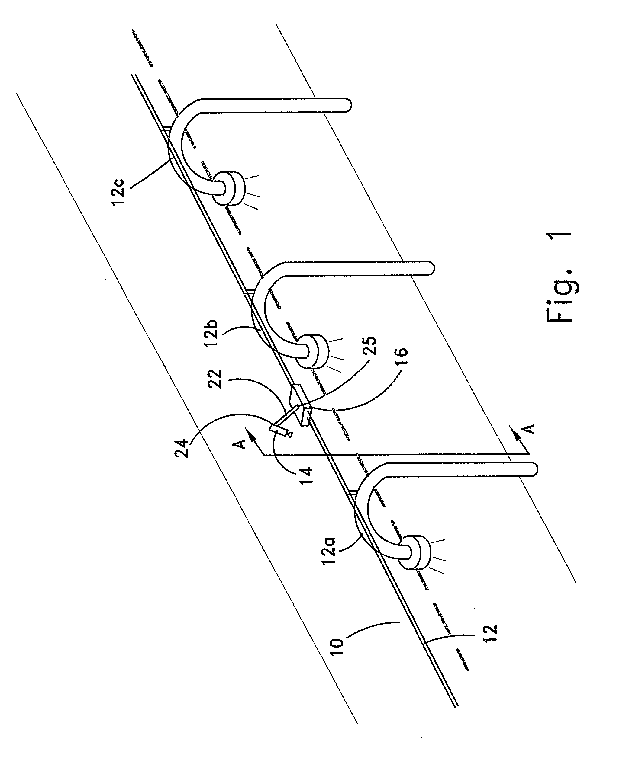
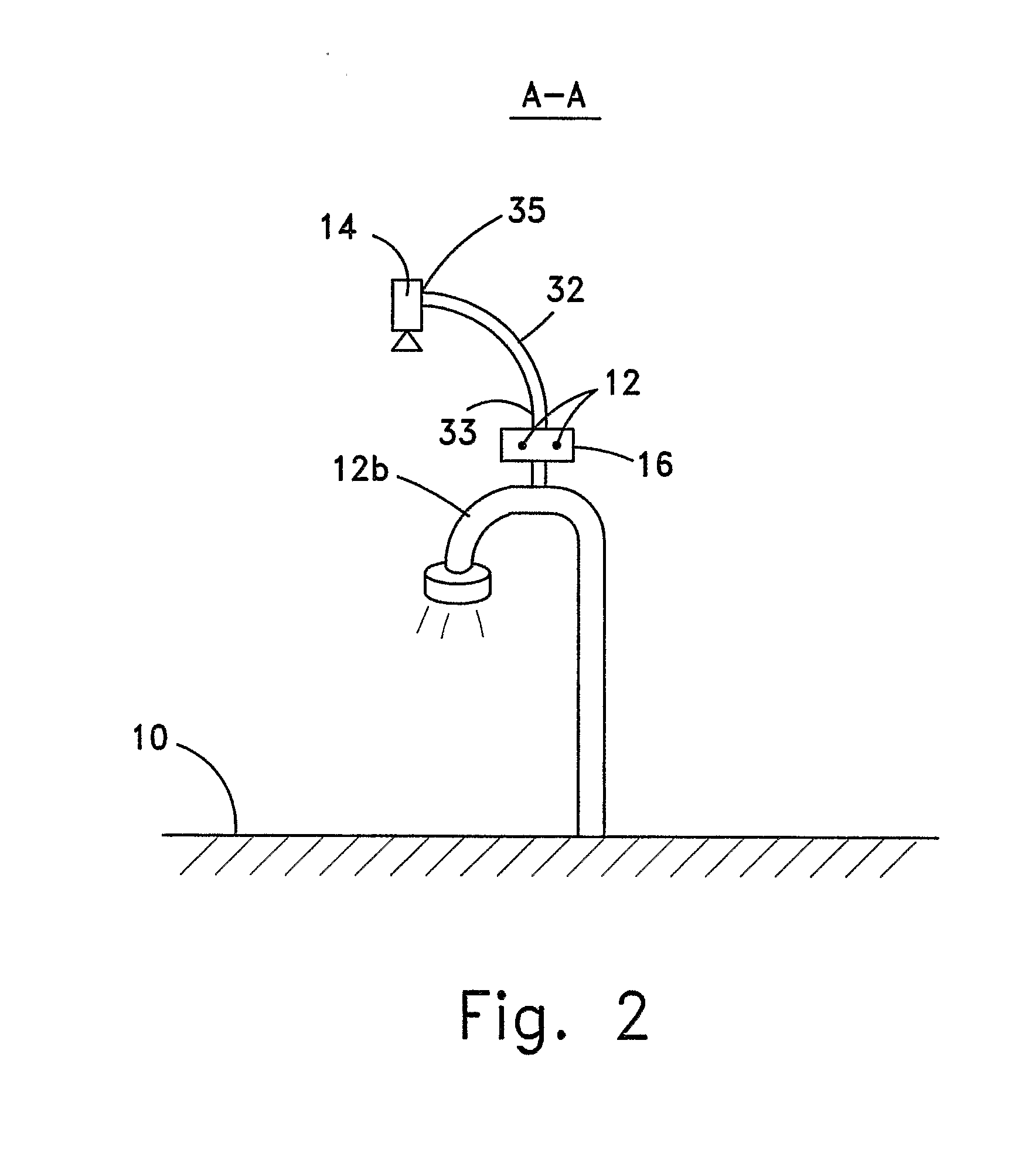
[0147]A first example of an application of the present invention is shown in FIGS. 1 through 8d. FIG. 1 shows a schematic perspective view of a two-lane highway (10) having light posts (12a), (12b), (12c) spaced apart along the length of one side of highway (10). According to a preferred embodiment of the present invention, mobile platform (16) travels along cable line (12) along the length of the highway (10), and has camera (14) connected thereto via a mechanical connection. In the first example, the mechanical connection takes the form of a rigid shaft (22). Rigid shaft (22) comprises an elongated rod made of a single member, which is joined, at one end (24), to camera (14), and, at the other end (25), to mobile platform (16). Rigid shaft (22) may be straight or curved, and is positioned such that one end (24) is elevated, preferably above highway (10). Ends (24),(25) may be fixedly joined to camera (14) and mobile platform (16) respectively, or ends (24),(25) may be rotatably jo...

third embodiment

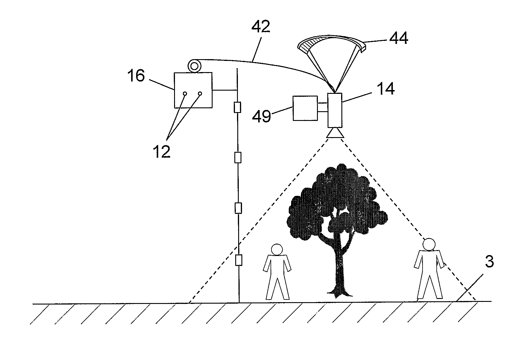
[0153]the first example of the present invention is shown schematically in FIG. 3, and comprises all the elements of the first embodiment as described above, mutatis mutandis, with the following differences. In this embodiment, the mechanical connection of the surveillance system is provided in the form of a woundable flexible cable (42). Additionally, camera (14) is mounted on a secondary platform that creates or is acted upon by aerodynamic lift forces, such as a helium balloon (45), a kite (not shown), a parachute (not shown), or a glider (not shown). The secondary platform is connected to mobile platform (16) via cable (42).

[0154]The position of camera (14) in FIG. 3 is controlled by the combination of the buoyant force (shown by arrow (46)) of helium balloon (45), which creates lift that forces balloon (45) upward, and motor (49), which is connected to a propulsion mechanism that causes balloon (45) to move in a horizontal direction (shown by arrow (48)), or hover with respect ...

fourth embodiment

[0158]the first example of the present invention is shown schematically in FIG. 4, and comprises all the elements of the first embodiment as described above, mutatis mutandis, with the following differences. In this embodiment, the mechanical connection of the surveillance system comprises a rigid shaft (52) having two members (52a), (52b), each pivotally joined, at one end, to each other, and at their other end, to camera (14) and to mobile platform (16), respectively. Alternatively, more than two shaft members may be present. The shaft members (52a), (52b) pivotably rotate about respective axes, as indicated by arrows (51). At least one motor (not shown) controls the movement of each shaft member (52a), (52b) and the camera (14) relative to each other.


PUM


Abstract

The present invention relates to a surveillance system for detecting forbidden movement in any direction at one or more locations along a road. The system comprises cameras that are in data communication with a control station for detecting the forbidden movement; mobile platforms that are movable along a desired path along the road; mechanical connectors for connecting the cameras to the mobile platforms, that create an adjustable projection of the spatial distance between the camera and the mobile platform; and a control station for receiving and processing data from and transferring data the cameras.

Description

FIELD OF THE INVENTION[0001]The present invention relates in general to a surveillance system. In particular, the present invention relates to a surveillance system for detecting forbidden movement that takes place along a predetermined path.BACKGROUND OF THE INVENTION[0002]There are many kinds of activities or movements that are generally forbidden, each of which may take place at a different location along a path and may violate one or more laws. One type of forbidden movement may take place along a road, by vehicle operators as well as by pedestrians. If left undetected, certain activities may directly or indirectly cause harm, resulting in monetary damages and / or physical injury.[0003]For instance, it is widely known that traffic violations, including improper lane changes, passing on the wrong side or without sufficient distance, following too closely (tailgating), failing to obey traffic signals, changing speed suddenly, traveling over the speed limit, turning from the wrong l...

Claims


Application Information

Patent Timeline
Patent Type & Authority Applications(United States)
IPC IPC(8): H04N7/18
CPCB60R11/04G08B13/19632G08B13/19623G08B13/196G08B13/00G08B13/22H04N7/18
Inventor RUBIN, OFER
Owner PLANUM VISION
Why Eureka
Try Eureka