
Stabilizer for robotic beating-heart surgery

Inactive Publication Date: 2005-02-10
INTUITIVE SURGICAL OPERATIONS INC
View PDF43 Cites 40 Cited by
  • Summary
  • Abstract
  • Description
  • Claims
  • Application Information

AI Technical Summary

Benefits of technology

[0013] The present invention provides surgical methods and devices which allow closed-chest surgery to be performed on a heart of a patient while the heart is beating. A region of the heart is often stabilized by engaging a surface of the heart with a stabilizer. The stabilizer can inhibit (i.e., substantially reduce) physiological motion of the stabilized region without having to stop the heart. While the stabilized region will not necessarily be absolutely still, motion of the target tissues can be inhibited sufficiently to treat the target tissues, particularly with robotic surgical tools which move in response to inputs of a robotic system operator. A stabilizing surface of the stabilizer will often be coupled to a drive system to position the surface from outside the patient, preferably by actuators of the robotic servomechanism, although manual manipulation from outside the body to position the stabilizer is also possible. Exemplary stabilizers include one or more sutures or other flexible and / or elastic tension members spanning between a pair of jointed bodies, thereby allowing the member to occlude a coronary blood vessel and / or help stabilize the target region between a pair of separated stabilizing surfaces.
[0014] In a first aspect, the invention provides a tissue stabilizer for use with a robotic surgical system to treat a target tissue within a patient body. The robotic surgical system has a plurality of manipulators with actuators for moving surgical end effectors in response to inputs by a system operator into an input device. The tissue stabilizer comprises a shaft having a proximal end and a distal end. A first stabilizer body has a stabilizing surface adapted to engage and inhibit movement of the target tissue. A joint couples the distal end of the shaft to the stabilizer, and a drive system is drivingly coupled to the joint so that the stabilizer body can be moved relative to the shaft from outside the patient body. The drive system may allow the stabilizer surface to be positioned using the actuators of a manipulator.
[0017] A flexible tension member can be attached to the first anchor and to the second anchor to engage the tissue between the first and second stabilizing surfaces. Optionally, movement of the first anchor away from the second anchor tensions the flexible member and can urge the flexible member against a tissue. Alternatively, the two anchors can be positioned relative to one another and then a flexible and / or elastic member can be positioned around the vessel to be occluded and attached to the already positioned anchors. This allows the flexible and / or elastic member to, for example, occlude and isolate a region of a blood vessel between the stabilizer bodies. By including a pair of anchors on each body, the target region of a blood vessel may be isolated from both upstream and downstream blood flow, greatly facilitating performing an anastomosis during a coronary artery bypass grafting procedure, or the like.

Problems solved by technology

Coronary artery disease remains the leading cause of morbidity and mortality in western societies.
While very effective in many cases, the use of open-heart surgery to perform coronary artery bypass grafting is highly traumatic to the patient.
Unfortunately, the proposed techniques for both minimally invasive cardiac surgery and beating-heart cardiac surgery significantly increase the difficulty of these already complex surgical procedures.
Formation of the anastomosis (the connection between the arterial source and the occluded artery) is quite challenging in a standard coronary artery bypass grafting procedure when the heart tissues are immobile and exposed for direct manipulation.
Even skilled surgeons may find it awkward and / or time consuming to instead perform such procedure in a minimally invasive manner or while the heart is beating.

Method used


Image

  • Stabilizer for robotic beating-heart surgery
  • Stabilizer for robotic beating-heart surgery
  • Stabilizer for robotic beating-heart surgery

Examples


Embodiment Construction

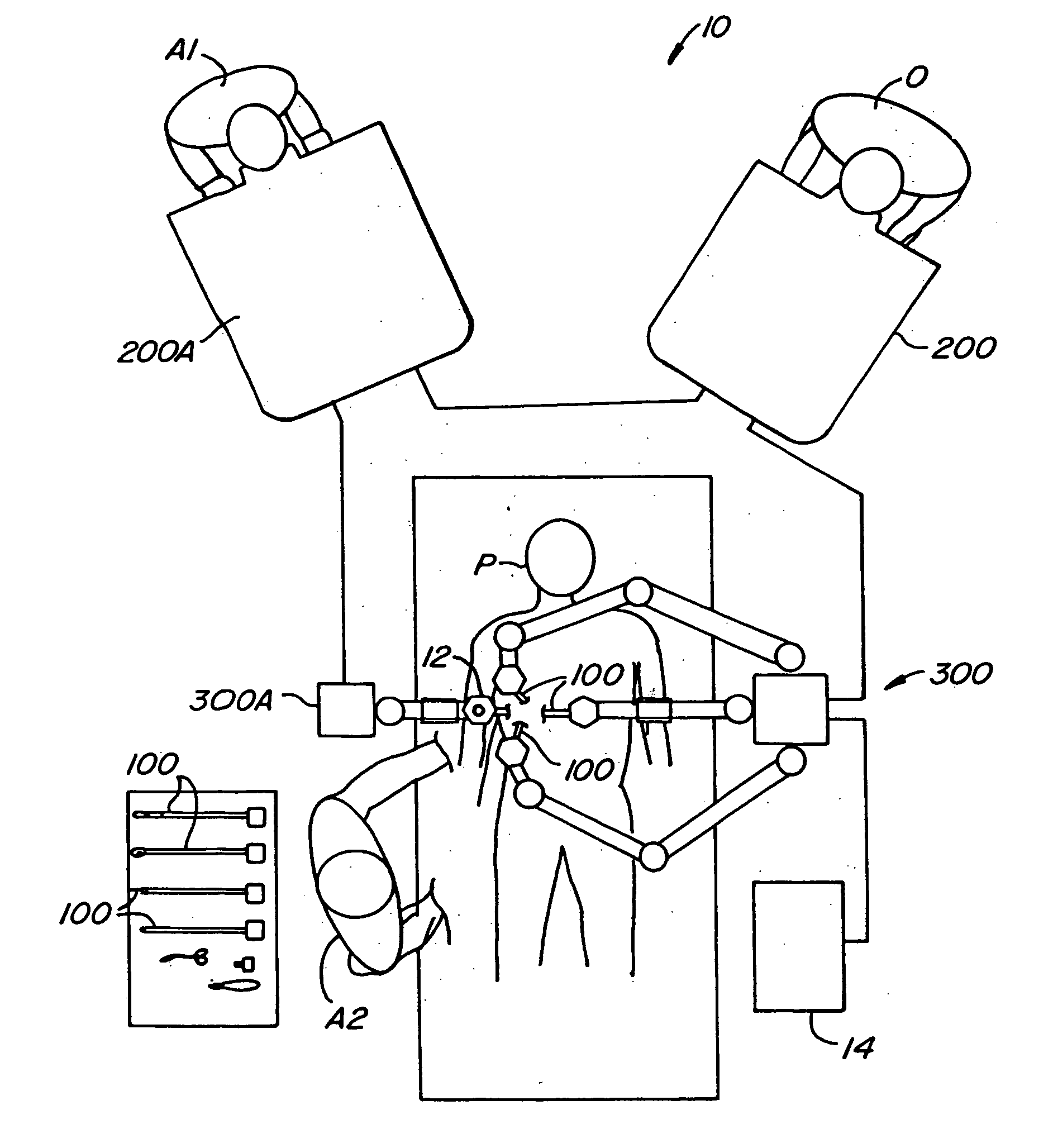
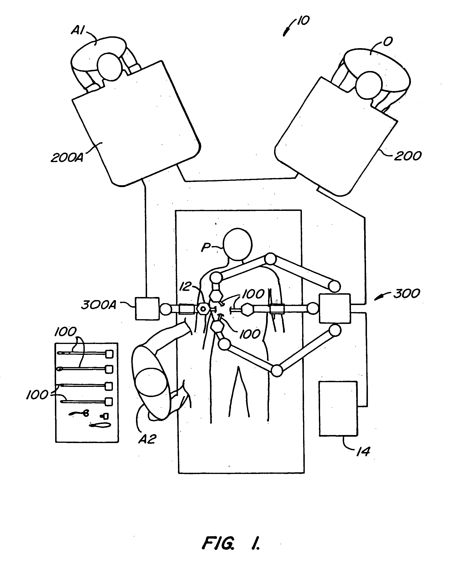
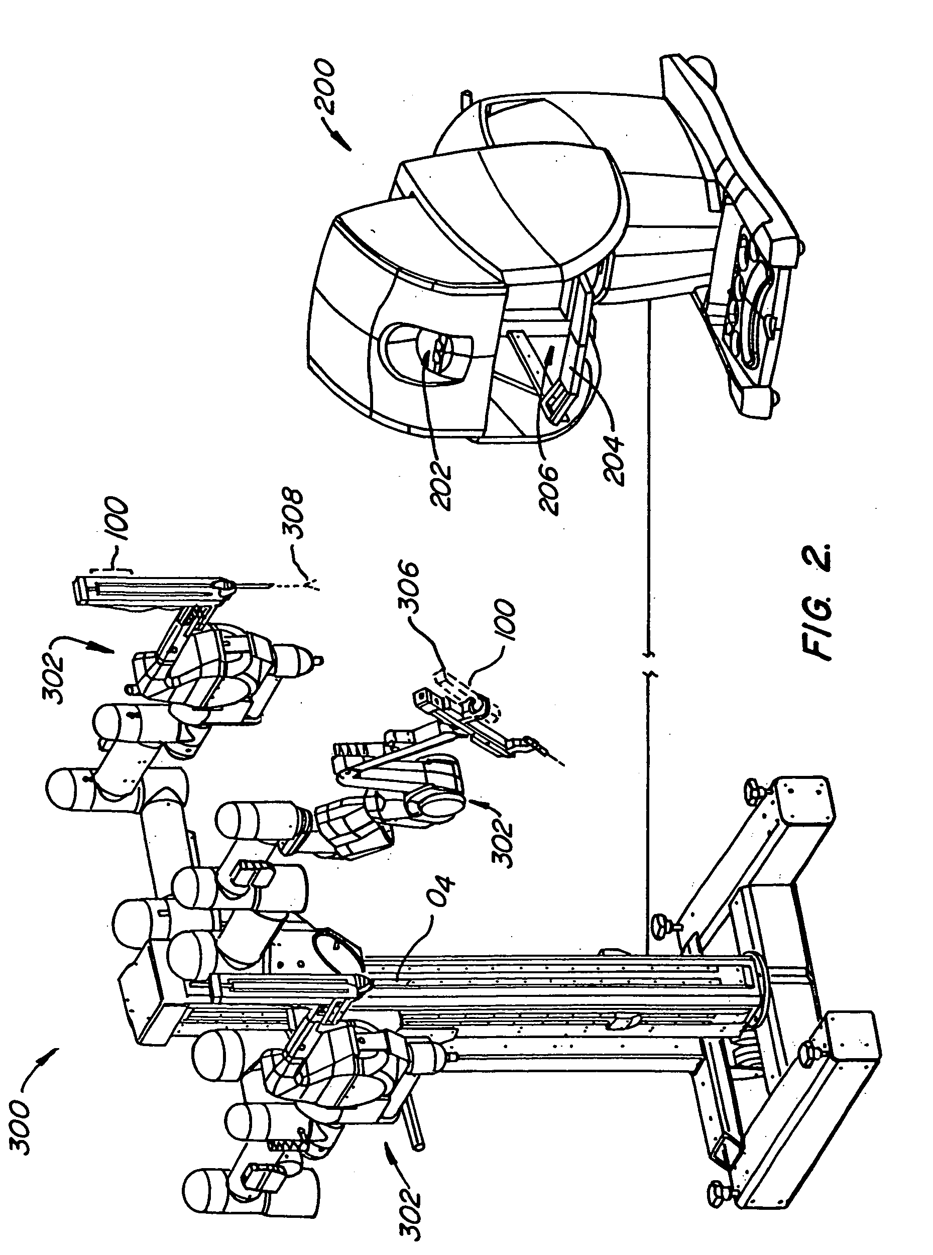
[0041] Referring now to FIG. 1, a robotic surgical system 10 includes a master control station 200 and a slave cart 300. Optionally, any of several other additional components may be included in the surgical system to enhance the capabilities of the robotic devices to perform complex surgical procedures. An operator O performs a minimally invasive surgical procedure at an internal surgical site within patient P using minimally invasive surgical instruments 100. Operator O works at master control station 200. Operator O views a display provided by the workstation and manipulates left and right input devices. The telesurgical system moves surgical instruments mounted on robotic arms of slave cart 300 in response to movement of the input devices. As described in co-pending U.S. patent application Ser. No. 09 / 433,120, filed on Nov. 3, 1999 (Attorney Docket No. 17516-004720), the full disclosure of which is incorporated herein by reference, a selectively designated “left” instrument is a...


PUM


Abstract

Surgical methods and devices allow closed-chest surgery to be performed on a heart of a patient while the heart is beating. A region of the heart is stabilized by engaging a surface of the heart with a stabilizer without having to stop the heart. Motion of the target tissues is inhibited sufficiently to treat the target tissues with robotic surgical tools which move in response to inputs of a robotic system operator. A stabilizing surface of the stabilizer is coupled to a drive system to position the surface from outside the patient, preferably by actuators of the robotic servomechanism. Exemplary stabilizers includes a suture or other flexible tension member spanning between a pair of jointed bodies, allowing the member to occlude a coronary blood vessel and / or help stabilize the target region between the stabilizing surfaces.

Description

CROSS-REFERENCES TO RELATED APPLICATIONS [0001] The present application is a continuation of and claims the benefit of priority from U.S. patent application Ser. No. 10 / 017,641 (Attorney Docket No. 017516-002531US), filed Dec. 14, 2001, which is a divisional of and claims the benefit of priority from U.S. patent application Ser. No. 09 / 436,524 (Attorney Docket No. 017516-002530US), filed Nov. 9, 1999; which is a continuation-in-part of and claims the benefit of priority from U.S. patent application Ser. No. 09 / 374,643 (Attorney Docket No. 017516-005900US), filed Aug. 16, 1999, and U.S. patent application Ser. No. 09 / 436,982 (Attorney Docket No. 017516-002520US), filed Nov. 9, 1999, which claims the benefit of priority from Provisional Application Ser. Nos. 60 / 109,301 (Attorney Docket No. 017516-001000US), filed Nov. 20, 1998; 60 / 109,303 (Attorney Docket No. 017516-001100US), filed Nov. 20, 1998; 60 / 109,359 (Attorney Docket No. 017516-002500US), filed Nov. 20, 1998; and 60 / 150,145 (A...

Claims


Application Information

Patent Timeline
IPC IPC(8): A61B17/00A61B17/04A61B19/00
CPCA61B17/04A61B17/0469A61B19/2203A61B19/5212A61B19/5244A61B2017/00243A61B2017/00477A61B2019/223A61B2019/2234A61B2019/2242A61B2019/2246A61B2019/2276A61B2019/2223A61B2034/715A61B2034/742A61B34/20A61B34/71A61B90/361A61B34/30A61B34/37A61B34/35A61B2034/305
Inventor RAMANS, ANDRIS D.ROSA, DAVID J.FALK, VOLKMAR
Owner INTUITIVE SURGICAL OPERATIONS INC
Learn More