Expandable interbody fusion cage with rotational insert

a fusion cage and expandable technology, applied in the field of expandable interbody fusion cages, can solve the problems of delay or impede fusion, compromising the integrity of the endplate, and compromising the clinical outcome of surgery, so as to facilitate the rotation of the insert, prevent unwanted motion, and prevent unwanted motion

Inactive Publication Date: 2012-02-07
STEVENS INSTITUTE OF TECHNOLOGY
View PDF43 Cites 83 Cited by
  • Summary
  • Abstract
  • Description
  • Claims
  • Application Information

AI Technical Summary

Benefits of technology

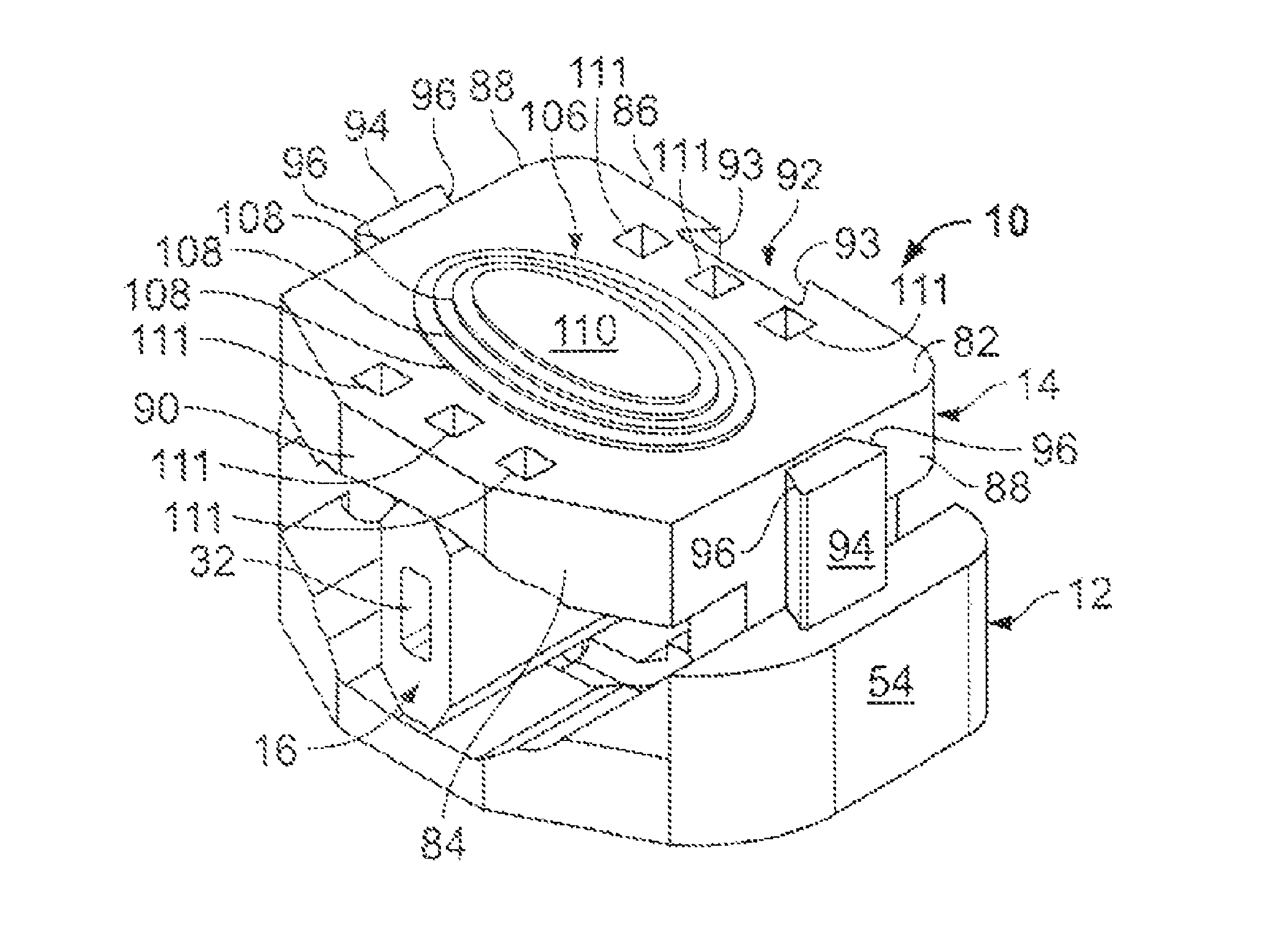
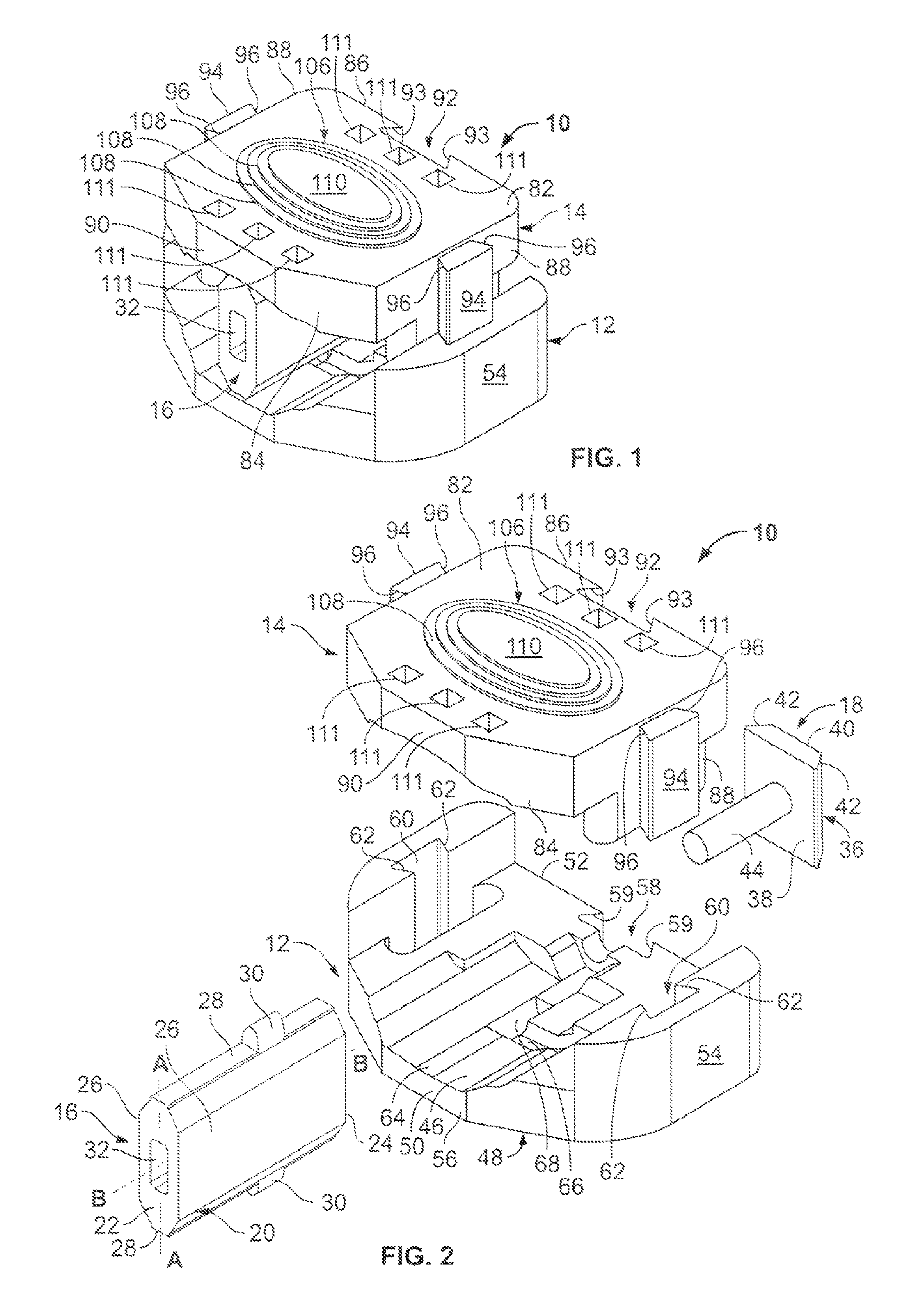
[0020]The present invention overcomes the disadvantages and shortcomings of the prior art discussed above by providing an expandable interbody fusion cage that includes an inferior baseplate, a superior baseplate, an insert mounted rotatably between the inferior and superior baseplates, and a guide peg that facilitates the rotation of the insert. Expansion of the cage is achieved by rotating the insert 90° within the inferior and superior baseplates from its initial collapsed position to its final expanded position. Each of the inferior and superior baseplates includes an external surface adapted for interaction with a vertebral body, and an internal portion adapted to house and guide the insert during rotation. The external surfaces of the inferior and superior baseplates incorporate geometry to match the natural shape and curvature of the vertebral endplate and gain purchase into the endplate to secure the cage in place. The external surface of the superior baseplate is also angled to account for the lordosis of the spine. The internal surfaces of the baseplates incorporate various grooves and curves so as to enclose the insert and prevent unwanted motion during its rotation. The baseplates are designed to interact with each other, being in constant contact once assembled to further guide the expansion and prevent unwanted motion.
[0022]The insert drives the expansion of the cage. In an embodiment, the insert is oval in shape and includes dog-eared, angled, flat edges. Such a size and shape allows for the insert's rotation to cause expansion of the cage, as the insert's major axis is longer than its minor axis. The insert is initially placed into the cage with its minor axis vertical, and is then rotated 90° so that its major axis becomes vertical. This rotation forces the two baseplates apart, thus expanding the cage. The insert is guided during the rotation by the guide peg and grooves within the internal surfaces of the inferior and superior baseplates. The insert is secured into its final conformation by pushing it posteriorly into another groove within the interior surfaces of the baseplates. In its locked position, the insert is prevented from dis-rotating and, thus avoids a collapse of the cage.
[0023]In an embodiment, each of the four main components described above are interchangeable, as they may consist of different sizes, shapes, etc., so as to allow for enhanced adjustability of the cage. The superior baseplate is selected to match the lordosis angle of the operated segment, and an insert is selected to achieve the desired final height once the cage is expanded. This adjustability enhances the fit and positioning of the cage.

Problems solved by technology

The amount of disc space distraction is a crucial aspect of the spinal fusion surgery; too little or too much distraction results in various complications that compromise the clinical outcome of the surgery.
However, the strong subchondral bone of the cortical endplate is partially removed, which compromises the endplate's integrity.
However, the endplate is minimally vascularized, which may delay or impede fusion.
The cage must also be precisely the correct height to match the disc space in order for implantation to occur; a factor that makes the implantation of these cages significantly difficult.
This extensive site preparation can damage the endplates, compromising the integrity of the vertebrae.
If the cage is too large or too small, the surgeon is forced to coerce the implant to fit into the disc space, risking a malpositioned cage and revision surgery.
An interbody fusion procedure is associated with a 5-10% risk of complication.
The more common, minor complications resulting from the fusion procedure include dural tears, ileus, superficial infections, and neurologic problems.
Other, more serious complications include subsidence, nonunion, device migration, and malpositioning.
These complications usually result in a revision surgery, in which the surgeon must perform a second procedure to remove the initial cage, repair any damage, and implant a new device.
This penetration itself can cause pain and lead to a loss of the disc space height that was originally achieved.
The loss of disk space height negates the implant and the spine is once again unstable.
This instability leads to revisions in an attempt to alleviate the pain and re-space the vertebrae again.
Subsidence also causes a narrowing of intervertebral foramen and loss of lordsosis, which further exacerbates patient discomfort and can impair the patient's balance.
An improperly sized implant may fail to gain adequate purchase into the bony endplates, leading to laxity and nonunion.
At micromotions above 24 μm, fibrous tissue ingrowth begins to occur, which impedes bone ingrowth and creates an improper fusion.
A cage that is not securely fixed to the adjacent vertebrae can migrate anteriorly or posteriorly, both of which have drastic effects.
During motion, the migrating implant can tear major vascular structures and organs, causing extensive complications and even death.
If the cage migrates posteriorly, it can shift into the medullary canal, damaging the spinal cord, causing paralysis and death.
A cage that is malpositioned is one that either does not appropriately fit the disc space or was implanted in an incorrect manner.
Malpositioning can be the result of a poorly designed cage, an inappropriate device selection, or surgeon error.
The faulty placement of the cage can result in decreased stability, which can cause pseudarthrosis or migration.
A cage that is inappropriately sized can increase the risk of subsidence or compress surrounding nerve roots.
Since the positioning of the cage is causing substantial complications, a malpositioned cage must be removed and replaced via a revision surgery.
The endplate preparation required to implant the cage also causes endplate abrasion and is further exacerbated during the implantation of the cage, in which the surgeon must coerce the implant into the disc space.
The shear stresses against the vertebrae erode the endplates, damaging their surfaces.
This trauma to the endplates initiates an inflammatory response, which can delay or inhibit fusion.
The lack of stability of the implant can then result in pseudarthrosis or migration, requiring a revision surgery.
During a fusion surgery, the intricate procedure required to implant the cage often leads to surgeon error.
A more common surgeon error is an inaccurate distraction of the intervertebral space.
Over-expansion can stretch and irritate the surrounding muscular and neural tissue, while too little expansion will not allow for adequate tensioning of the ligamentous apparatus, decreasing the stability of the cage.
Height will be measured again during surgery, but once the cage is implanted, the height cannot be adjusted.
Over-distraction from implants that are too tall will stretch the surrounding neural and muscular tissue, causing irritation.
The widened disc space will also compress the adjacent discs, placing them under abnormal stresses and depleting their shock absorbing function.
An implant that is too small will fail to gain sufficient purchase into the vertebral endplates, resulting in pseudarthrosis and possibly migration.
In both cases, the risk of malpositioning is increased, since the implant is inherently poorly suited for the intended space.
The revision surgery is strenuous for both the surgeon and patient.
The revision surgery also increases health care costs, requiring the hospital to spend substantial funds.
A significant portion of complications that lead to a revision surgery are caused by a mismatch between the intervertebral height and fusion cage, which is mostly due to the fixed height nature of the current cages.
Since the surgeon must determine the height of the cage before implantation, any error in this measurement will result in a mismatch between cage and disc space height.
Even if the cage is sized appropriately, some coercion is needed to impact the cage into the disc space, resulting in endplate abrasion and possible malposition.
To summarize, current fixed cages present the potential problems of abrasion, subsidence, malpositioning, pseudoarthritis, and even cage migration, all of which create potential further future expense and pain for patients and clinicians by means of the need for revision surgeries.

Method used


Image

  • Expandable interbody fusion cage with rotational insert
  • Expandable interbody fusion cage with rotational insert
  • Expandable interbody fusion cage with rotational insert

Examples


Embodiment Construction

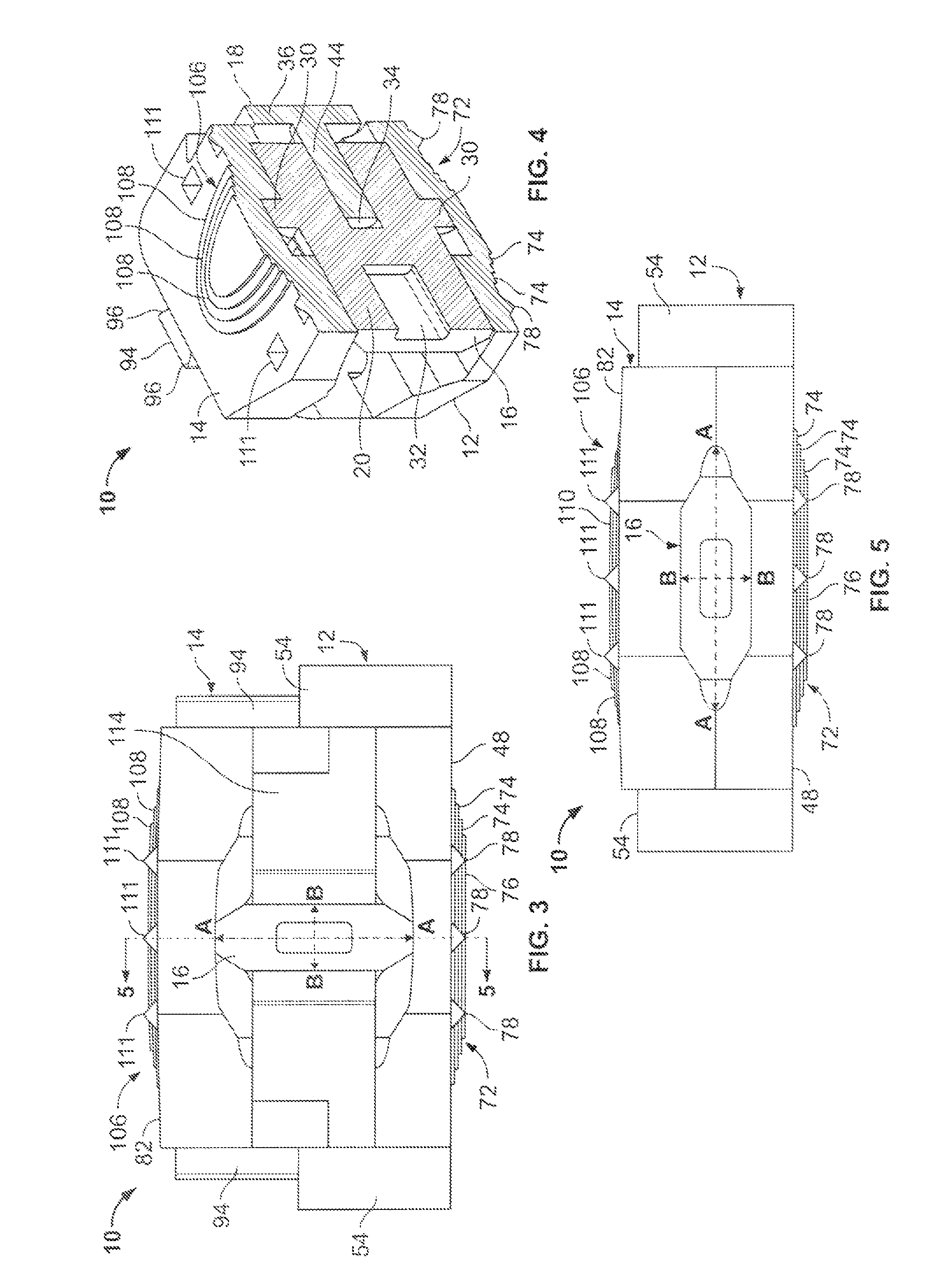
[0035]Referring to FIGS. 1 through 5, a fusion cage 10 includes an inferior baseplate 12 and a superior baseplate 14 which is movably connected to the inferior baseplate 12, an insert 16, and a guide peg 18 (see FIGS. 2 and 4). The insert 16 is rotatably assembled to the guide peg 18, and is positioned between the inferior and superior baseplates 12, 14 for purposes that are described below. The cage 10 is adapted to expand from a contracted (i.e., collapsed) position, as shown in FIG. 5, to an expanded position, as shown in FIG. 1.

[0036]Referring to FIGS. 2 and 4, the insert 16 includes a body 20 that has proximal and distal ends 22, 24, side surfaces 26 that extend parallel to major axis A-A of the insert 16, and surfaces 28 that extend parallel to minor axis B-B of the insert 16. Protuberances 30 extend outwardly from the surfaces 28. A rectangular-shaped cavity 32 is formed within the proximal end 22 of the insert 16 to accept the insertion of a tip of a screw-driver like hand t...


PUM


Abstract

An expandable intervertebral fusion cage that includes an inferior baseplate and a superior baseplate, an insert rotatably received between the inferior and superior baseplates, and a guide pin coupled to the inferior and superior baseplates for facilitating the rotation of the insert. The insert includes a pair of protuberances, each of which are releasably engageable with a corresponding lock groove formed within the inferior and superior baseplates. When said insert is rotated relative to the guide pin, the protuberances engage the lock grooves, and the inferior and superior baseplates expand from a collapsed position, in which said inferior and superior baseplates are juxtaposed with one another, and an expanded position, in which said inferior and superior baseplates are diverged away from one another. Tabs formed on the superior baseplate continuously engage slots formed within the inferior baseplate when the baseplates expand from their collapsed position to their expanded position.

Description

CROSS-REFERENCE TO RELATED APPLICATION[0001]This application is a Section 111(a) application relating to commonly owned, U.S. Provisional Application Ser. No. 61 / 090,769 entitled “EXPANDABLE INTERBODY FUSION CAGE WITH ROTATIONAL INSERT” filed Aug. 21, 2008.FIELD OF THE INVENTION[0002]The present invention relates to medical devices used in orthopaedic spinal fusion procedures and, more particularly, expandable interbody fusion cages used in spinal fusion procedures.BACKGROUND OF THE INVENTION[0003]Annually, there are approximately 300,000 fusion surgeries performed in the United States. Numerous types of spinal fusion cages exist, varying in design, material, size, and implantation method. Regardless of the type of cage used, a full or partial discectomy is performed prior to implantation. Once the necessary portion of a spinal disc is removed, the disc space is then expanded using a distracter. In order to accept a cage, the disc space must be distracted so that the intervertebral ...

Claims


Application Information

Patent Timeline
Patent Type & Authority Patents(United States)
IPC IPC(8): A61F2/44
CPCA61F2/447A61F2/28A61F2002/3038A61F2002/30387A61F2002/30471A61F2002/30518A61F2002/30579A61F2002/30843A61F2002/30897A61F2002/4475A61F2220/0025A61F2220/0033A61F2220/0091A61F2002/30331A61F2002/30593
Inventor VALDEVIT, ANTONIOHAZELWOOD, VIKKIGADOL, STEVEN J.HARDENBROOK, FREDERICK H.KOWALSKI, WILLIAM J.QUIRAY, ADRIENNE G.TRAPANI, MICHAEL A.
Owner STEVENS INSTITUTE OF TECHNOLOGY
Why Eureka
Try Eureka