Fixing structure of drawing electronic assembly

A technology for electronic components and fixed structures, applied in the field of fixed structures and electronic devices, can solve the problems of a large number of screws, labor and time, etc., and achieve the effect of reducing assembly time

Active Publication Date: 2007-08-01
ASUSTEK COMPUTER INC
View PDF3 Cites 2 Cited by
  • Summary
  • Abstract
  • Description
  • Claims
  • Application Information

AI Technical Summary

Problems solved by technology

[0006] In view of the above problems, the object of the present invention is to overcome the deficiencies and defects of the prior art, and provide a screw-free fixing structure that can solve the shortcomings of requiring a large number of screws and assembling labor and time, for fixing a removable electronic component The fixed structure and electronic device

Method used


Image

  • Fixing structure of drawing electronic assembly
  • Fixing structure of drawing electronic assembly
  • Fixing structure of drawing electronic assembly

Examples


Embodiment Construction

[0046] In order to make the content of the present invention easier to understand, the preferred embodiments of the fixing structure of the removable electronic component and the electronic device of the present invention will be described below with reference to the relevant drawings.

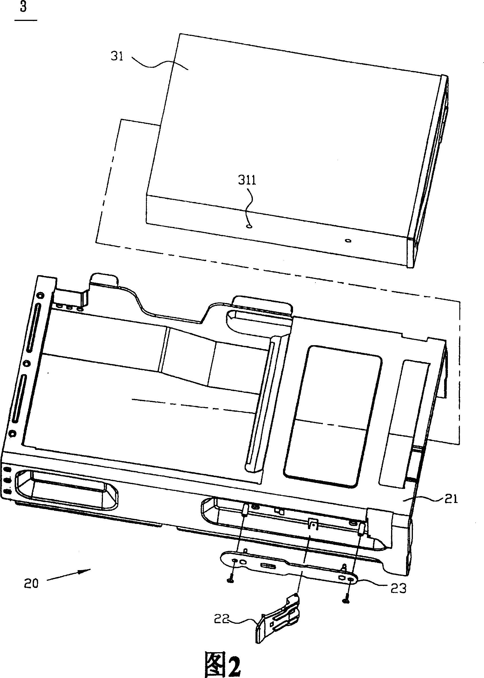
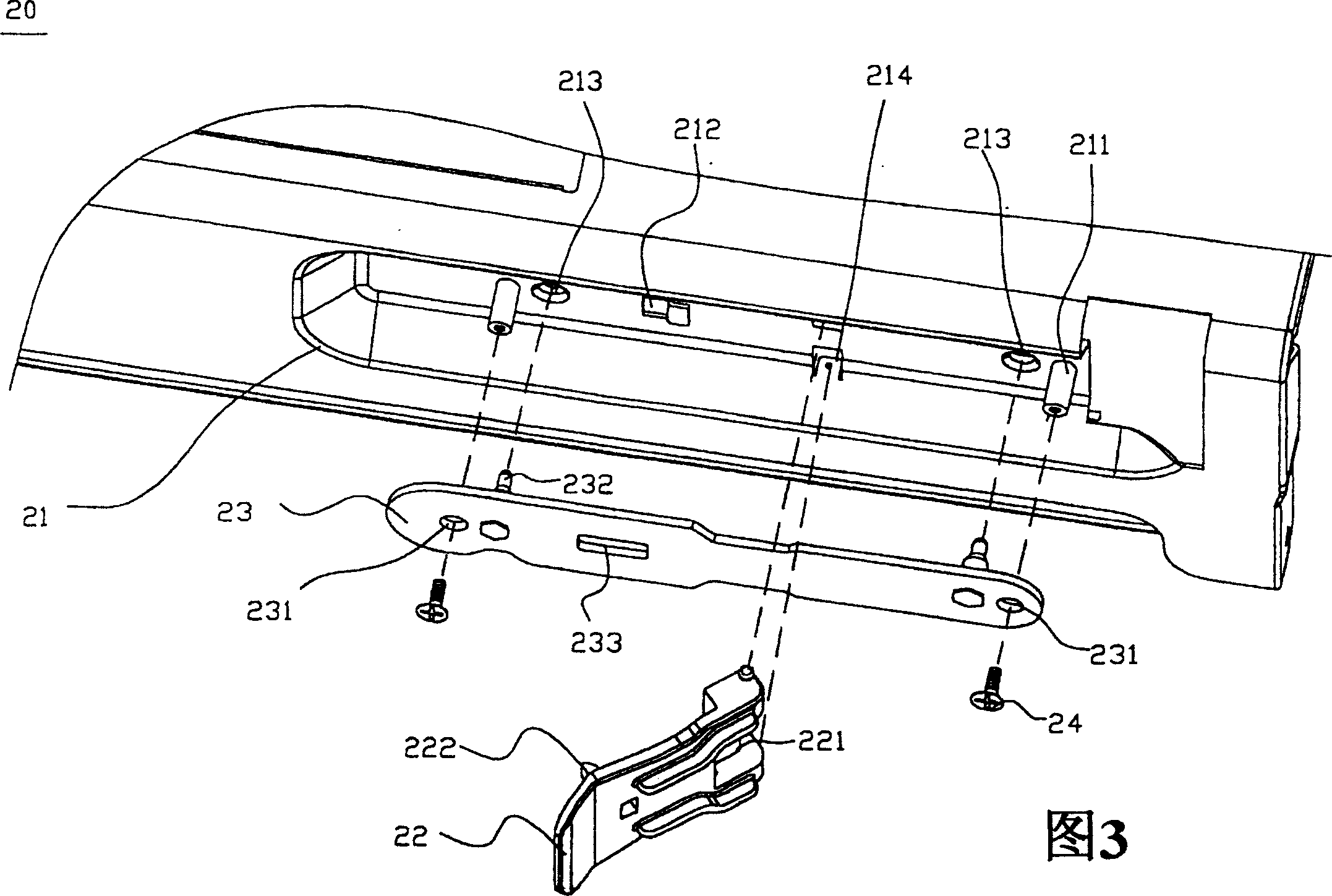
[0047] First, please refer to FIG. 2 to FIG. 7 to illustrate a preferred embodiment of the fixing structure of the removable electronic component of the present invention.

[0048] As shown in FIG. 2 , the fixing structure 20 of the removable electronic component is used for fixing a removable electronic component 31 , and the removable electronic component 31 has at least one first opening 311 . Wherein, the removable electronic component 31 can be a hard disk drive, or an optical drive and so on. In this embodiment, the removable electronic component 31 is taken as an example of a hard disk drive.

[0049] The fixed structure 20 includes a casing 21 , a first movable part 22 , and a second ...


PUM


Abstract

A fixing structure of drawing electronic component consists of the first hole on electronic component ; a shell including guide column , the first clutch and buckle part and opening opposite to the first hole ; the first active piece including the second opening , the second clutch and buckle part ; and the second active piece including the third opening an a convex part . It is featured as connecting the first active piece to shell by pin joint, moving the second active part around the first one along guide column to let convex part insert into the first opening and hole.

Description

technical field [0001] The invention relates to a fixing structure and an electronic device, in particular to a screw-free fixing structure of an electronic component, that is, a fixing structure of an extractable electronic component. Background technique [0002] In the era of information explosion, the hard disk drive can be said to be the most important storage device in the computer. It provides low-cost, high-speed and large-capacity storage space, which can be used to store operating systems, application programs, and user data, etc. . [0003] Generally, removable hard drives need to be pre-fixed in a frame, which is a part of the host. As shown in FIG. 1 , a traditional removable hard disk drive 11 is accommodated in a frame 12 . The side of the frame 12 has several screw holes 121 , the screw holes 121 correspond to the fixing holes 111 on the side of the hard drive 11 , so that the frame 12 and the hard drive 11 can be locked and combined by screws 13 . [0004...

Claims


Application Information

Patent Timeline
Patent Type & Authority Patents(China)
IPC IPC(8): G06F1/18
Inventor 周全昌
Owner ASUSTEK COMPUTER INC
Why Eureka
Try Eureka