Electric soldering iron

An electric soldering iron and handle technology, applied in soldering irons, metal processing equipment, manufacturing tools, etc., can solve the problems of easy loss of brackets, unsatisfactory fixing effect, wear of bayonet, etc., and achieve the effect of simple operation.

Active Publication Date: 2013-10-16
安徽苏立科技股份有限公司
View PDF10 Cites 1 Cited by
  • Summary
  • Abstract
  • Description
  • Claims
  • Application Information

AI Technical Summary

Problems solved by technology

But the bracket is easy to lose, and after long-term use, it will ca

Method used


Image

  • Electric soldering iron
  • Electric soldering iron
  • Electric soldering iron

Examples


Embodiment Construction

[0015] The present invention will be further described below in conjunction with the accompanying drawings.

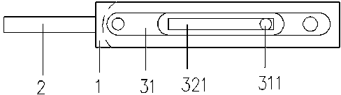
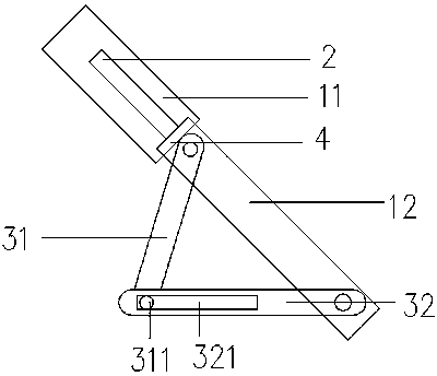
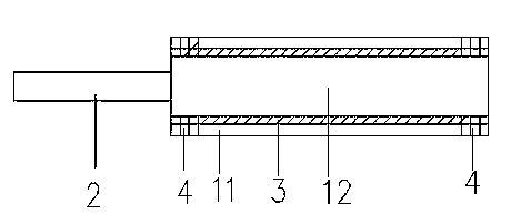
[0016] As shown in the figure, an electric soldering iron includes a handle 1 and a soldering nozzle 2. The soldering nozzle 2 is fixed on the left end of the handle 1. The handle is provided with two layers of shells, the two ends of the outer shell 11 and the inner shell 12. The card slots 4 that cooperate with each other are respectively provided, and the two layers of shells are slidably connected and fixed through the card slots 4; two movable brackets 3 are installed between the two layers of shells, and the brackets are relatively installed on both sides of the handle. side.

[0017] The bracket 3 is composed of a first support bar 31 and a second support bar 32. One end of the first support bar 31 is rotatably fixed to the left end of the inner shell of the handle, and the other end is provided with a circular sliding button 311; One end of the second support ...


PUM


Abstract

The invention relates to an electric soldering iron which comprises a handle and an ironing mouth, wherein the ironing mouth is fixed at the left end of the handle; the handle is provided with two layers of casings; two movable brackets are mounted between the two casings; the brackets are oppositely mounted on two sides of the handle. According to the electric soldering iron, the movable brackets are arranged in the electric soldering iron, so as to be convenient to carry and easy to keep; meanwhile, the electric soldering iron has the effect of scald resistance.

Description

technical field [0001] The invention relates to a tool for welding electronic components, in particular to an electric soldering iron. Background technique [0002] The electric soldering iron is a tool for welding integrated components. When in use, the electric soldering iron is energized to heat the soldering core to melt the solder to solder the pins of the electronic components. The electric soldering iron used in daily life is equipped with a bracket in order to prevent the operator from being scalded by the high-temperature soldering core when not in use or burn out the article, but this bracket is generally all heavy and expensive, and is not easy to store. [0003] In the existing technology, a kind of electric soldering iron whose patent number is "03264955.X" includes a handle, a bracket, a soldering nozzle and a soldering core, and is characterized in that it also includes a bracket, and the bracket is provided with a bayonet. A slot matching the shape of the ba...

Claims


Application Information

Patent Timeline
IPC IPC(8): B23K3/03
Inventor 张敏
Owner 安徽苏立科技股份有限公司
Why Eureka
Try Eureka