
Cylinder lock body

A lock body, cylindrical technology is applied in the field of cylinder lock bodies, which can solve the problems of increasing the strength and fracture of the cylinder lock body.

Inactive Publication Date: 2007-08-15
MOTTURA SERRATURE DI SICUREZZA SPA
View PDF1 Cites 0 Cited by
  • Summary
  • Abstract
  • Description
  • Claims
  • Application Information

AI Technical Summary

Problems solved by technology

Therefore, according to the prior art, the problem that this device needs to solve is that the strength of the cylinder lock body needs to be increased at the said bridge.
In addition, the lock body is usually made of brass, so when subjected to bending deformation, for example, when a thief uses a tool to pry one of the two half-shells to make it alternately swing up and down, the said weak bridge represented part will break

Method used


Image

  • Cylinder lock body
  • Cylinder lock body

Examples


Embodiment Construction

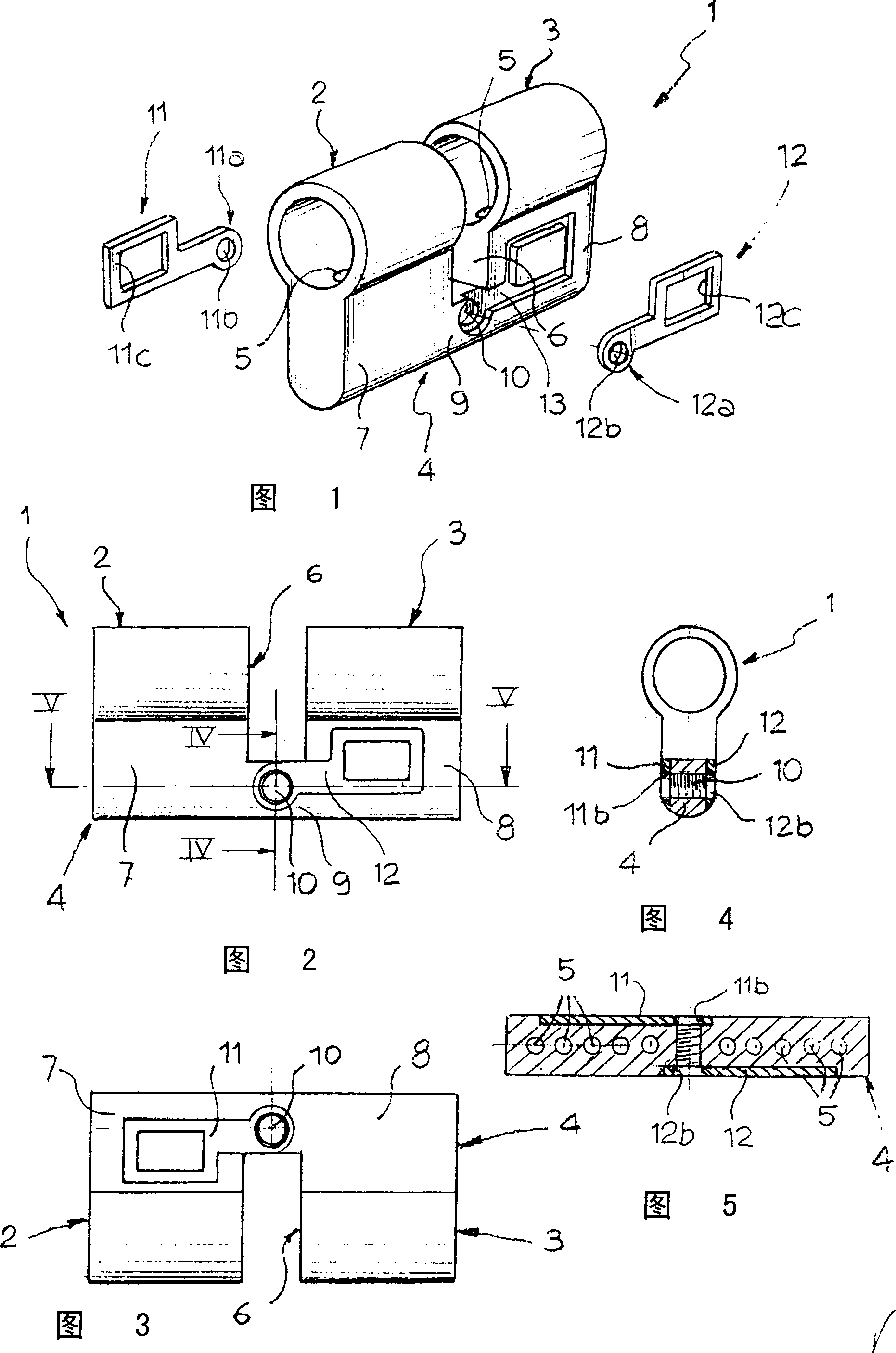
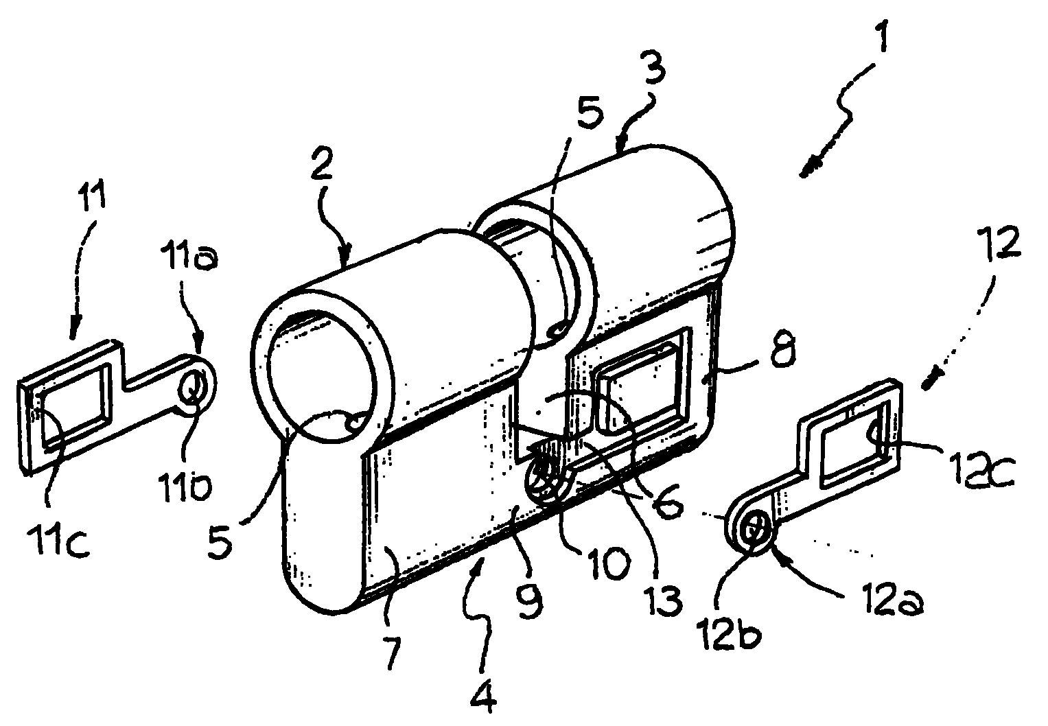
[0011] Referring to the drawings, it can be seen that the cylindrical lock body 1 has two opposite and coaxial cylindrical half-shells 2, 3 ready to receive a cylindrical lock cylinder (not shown). A flange 4 protrudes from one side of the cylindrical half-shells 2, 3, in which some small holes 5 are formed to receive cylinder lock tumblers (also not shown) according to known techniques, these small holes Holes are made in the inner cavities of the cylindrical half-shells 2,3.

[0012] The two half-shells 2, 3 are separated from each other by a notch 6 intended to be occupied by a rotatable pawl (not shown) of the lock, which notch also extends through a part of the flange 4, forming the two half-shells. Flanges 7, 8, which are connected together by a bridge 9.

[0013] The above shapes are familiar and conventional in the art. Also according to the prior art, there is also a threaded through-hole 10 on the bridge 9 for engaging a screw (not shown) to secure the lock body to...


PUM


Abstract

A cylinder lock body comprises two cylindrical half-housings (2, 3) with two respective half-flanges (7, 8) connected by a bridge-like portion (9) in which a hole (10) is formed for a cylinder lock fixing screw. On one face of one of the two half-flanges (7, 8) and on the opposite face of the other half-flange there are secured two reinforcing elements (11, 12) which have a portion (11a, 12a) surrounding the hole (10) for the fixing screw. Each reinforcing element extends only on one of the two half-flanges, so that in case of flexural rupture of the lock body at the bridge-like portion (9), the two half-housings (2, 3) cannot be fully separated from each other, since the respective reinforcing elements (11, 12) freely rotatably engage the fixing screw with their highlet-shaped ends (11a, 12a).

Description

technical field [0001] The present invention relates to cylinder locks, and in particular to cylinder locks of the type, the body of which has two opposed coaxial cylindrical half-shells for receiving a cylindrical lock cylinder, a flange extending from the half-shells. One side of the body protrudes, and some small holes are formed in the cylindrical half shell for loading the cylinder lock stopper. The two cylindrical half shells are separated by a gap, and the gap is intended to Occupied by the rotatable jaws of the lock, said notch extends into the flange, thus forming two semi-flanges adjoining the cylindrical half-shells, which are connected to each other by a bridge, inside said bridge A hole is formed for engaging the set screw of the lock, and the cylindrical lock body also includes two reinforcements fitted on opposite surfaces of the flange, each reinforcement having a portion around the hole. Background technique [0002] A cylinder lock body having the feature...

Claims


Application Information

Patent Timeline
IPC IPC(8): E05B9/10
CPCE05B9/048
Inventor S·莫特图拉
Owner MOTTURA SERRATURE DI SICUREZZA SPA
Learn More