
soft start valve

A soft-start, valve core technology, applied in safety valves, balance valves, valve devices, etc., can solve problems such as excessive pressure rise in the push chamber, breakage of the push-pull head, and impact at the connection of the push-pull head, so as to avoid excessive pressure increase. , Avoid frequent opening, avoid the effect of bending and breaking

Active Publication Date: 2015-09-09
CHENGDU HANGTIAN PHOTOELECTRIC TECH
View PDF6 Cites 0 Cited by
  • Summary
  • Abstract
  • Description
  • Claims
  • Application Information

AI Technical Summary

Problems solved by technology

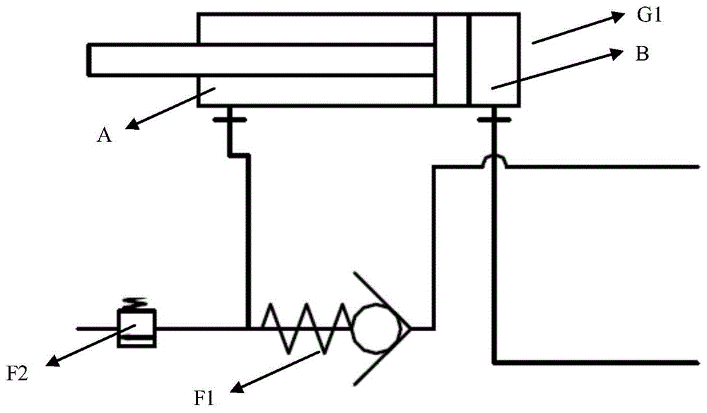
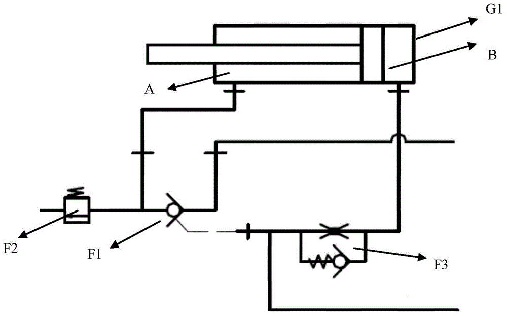
[0003] The above-mentioned hydraulic control check valve F1 has the following disadvantages: First, the hydraulic control check valve F1 locks the push cavity A of the push cylinder G1. There is a certain cross-sectional area ratio with the push chamber A, which is generally about 1:2. Therefore, opening the push chamber A will generally lag behind, which will easily cause the pressure of the push chamber to rise too fast, and the safety valve will be opened frequently, seriously affecting the use of the safety valve. service life; secondly, because the bracket cavity B of the push cylinder G1 is connected to the reversing valve of the main valve group, the flow of the reversing valve is relatively large, which may easily cause a large impact on the connection between the push-pull head of the push cylinder G1 and the push-pull head of the bracket, which may easily cause pinching. The bending fracture of the sub and the fracture of the push-pull head of the push cylinder G1

Method used


Image

  • soft start valve
  • soft start valve
  • soft start valve

Examples


Embodiment Construction

[0017] In order to make the object, technical solution and advantages of the present invention clearer, the present invention will be further described in detail below in conjunction with the accompanying drawings and embodiments. It should be understood that the specific embodiments described here are only used to explain the present invention, not to limit the present invention.

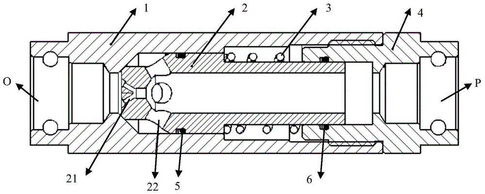
[0018] Such as figure 2 As shown, the soft start valve in this embodiment includes a housing 1, a valve core 2, a spring 3 and a connector 4. The housing 1 is a cylinder with a stepped hole inside, and the valve core 2 is a cylinder with a cavity inside. A cylinder, the front end of the valve core 2 is provided with a number of throttle holes 21 and a number of flow holes 22, the valve core 2 is installed inside the housing 1 and the front end of the valve core 2 is against the smallest inner diameter of the housing 1, The spring 3 is sleeved on the outside of the valve core 2, the connector 4 is...


PUM


Abstract

The invention discloses a soft starting valve which comprises a casing, a valve element, a spring and a connector. The casing is a cylinder internally provided with a step hole, the valve element is a cylinder internally provided with a cavity, a plurality of throttling holes and a plurality of overflowing holes are formed in the front end of the valve element, the valve element is installed in the casing, the front end of the valve element butts against the position of the minimum diameter of the casing, the valve element is sleeved with the spring, the connector is of a step hole structure, the head end of the connector is arranged at the tail end of the valve element in a sleeved mode, the head end of the connector is in interference fit with the tail end of the casing, the head end of the casing is a pushing oil cylinder pull frame cavity connector, and the tail end of the connector is provided with a main valve group reversing valve connector. According to the soft starting valve, when a hydraulic support is used for pulling a frame, through the throttling effect of the throttling holes, slow frame pulling can be achieved. On one hand, fast pressurizing of a pushing oil cylinder sliding cavity is effectively avoided, frequent starting of a safety valve is avoided, and the service life of the safety valve is prolonged; on the other hand, liquid flow entering a pull frame cavity from the main valve group steering valve is effectively controlled.

Description

technical field [0001] The invention relates to the technical field of valves, in particular to a soft-start valve used for a coal mine hydraulic support push frame. Background technique [0002] At present, many coal mine hydraulic support moving jacks adopt the way of flipping, which can increase the tension force and reduce the pushing force appropriately. The principle is as follows figure 1 As shown, the pushing chamber A of the pushing cylinder G1 of the pushing jack is equipped with a hydraulic control check valve F1 and a safety valve F2. Under the action of the hydraulic control check valve F1, the oil in the lower cavity of the oil cylinder returns through the oil inlet to realize the action of the oil cylinder; the function of the safety valve F2 is to control the direction of the liquid flow and cut off the closed high-pressure liquid in time to protect the conveyor and the push rod of the bracket structural safety. [0003] The above-mentioned hydraulic contro...

Claims


Application Information

Patent Timeline
Patent Type & Authority Patents(China)
IPC IPC(8): E21D23/18F16K17/30
Inventor 刘均李晓琦张列源赵红刘志霞
Owner CHENGDU HANGTIAN PHOTOELECTRIC TECH
Learn More