Switch for refrigerator door

A door switch and refrigerator door technology, applied in the field of door switches for lamps, can solve the problems of increasing power consumption and the like

Inactive Publication Date: 2002-01-23
LG ELECTRONICS INC
View PDF0 Cites 9 Cited by
  • Summary
  • Abstract
  • Description
  • Claims
  • Application Information

AI Technical Summary

Problems solved by technology

[0018] That is, no additional device is installed to turn off the light when the door is open and the user does not want to turn on the ligh

Method used


Image

  • Switch for refrigerator door
  • Switch for refrigerator door
  • Switch for refrigerator door

Examples


Embodiment Construction

[0036] best practice

[0037] Preferred embodiments of the present invention will now be described in detail, examples of which are illustrated in the accompanying drawings.

[0038] refer to Figure 3 to Figure 6 A refrigerator door switch according to a first embodiment of the present invention will be described.

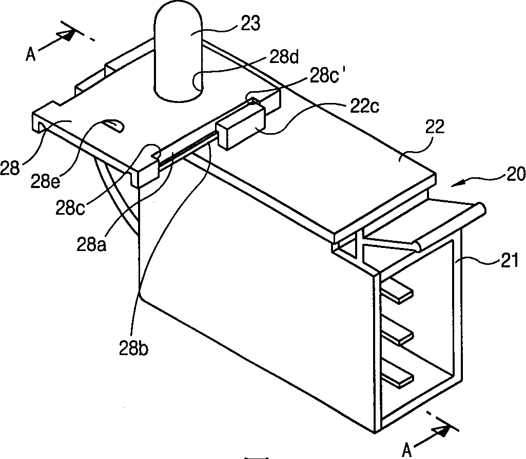
[0039] image 3 and 4 represent the working state of the door switch when the door is opened. image 3 It is a perspective view showing the refrigerator door switch of the present invention, and Fig. 4 is along image 3 Sectional view of line A-A.

[0040] in addition, Figure 5 with 6 Indicates the working state of the door switch off. Figure 5 It is a perspective view showing the door switch of the present invention, Image 6 is along Figure 5 Sectional view of line B-B in middle.

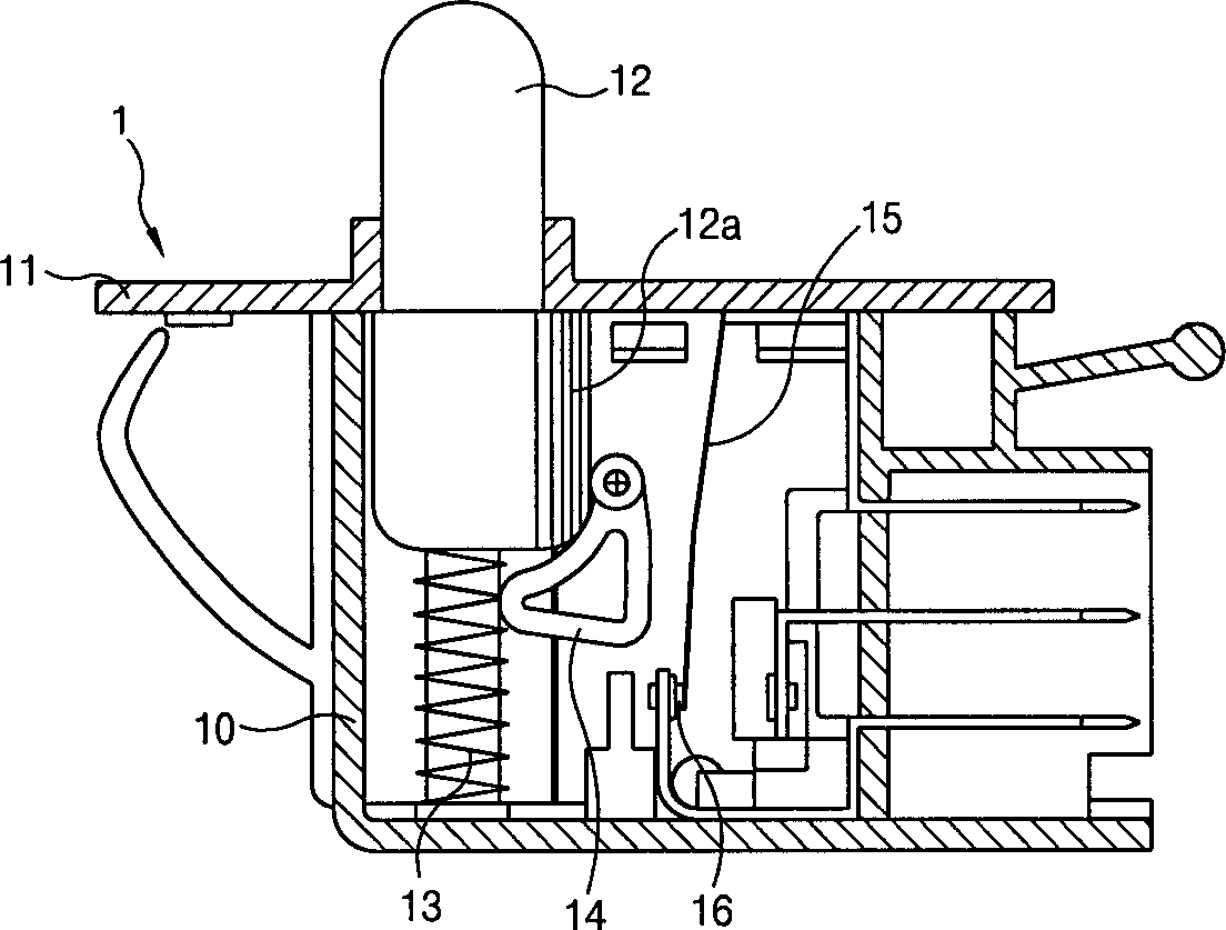
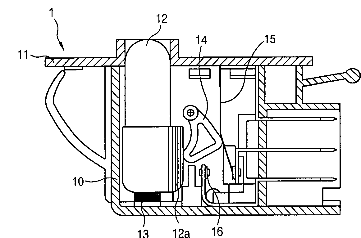
[0041] The structure of the door switch of the present invention is that the pressing rod 23 protruding upwards from the box 20 moves to the inside or outside of the box ...


PUM


Abstract

A door switch for a refrigerator includes a case having a hole on one side; switch terminal units installed inside the case and making on/off operations of a circuit; a plunger for changing the on/off operations of the circuit mechanically while moving inward/outward of the case through the hole on the case; and a restriction means installed on the case for restricting the movement of the plunger, whereby a chamber light can be turned off even if the door of refrigerator is opened, and therefore power consumption of the refrigerator can be reduced.

Description

field of invention [0001] The present invention relates to a refrigerator door switch, and more particularly, to a door switch that turns on / off a lamp in a refrigerator according to opening / closing of a door. Background technique [0002] Generally, a room light is installed inside a refrigerator so that a user can recognize items stored in the refrigerator by turning on the light when the door of the refrigerator is opened. [0003] The above lamp is turned on / off according to the operation of the door switch installed on the inner wall of the refrigerator or the front of the main body, and the lamp can be turned on when the switch is turned on. [0004] figure 1 with figure 2 It is a longitudinal sectional view showing a conventional refrigerator door switch. [0005] Such as figure 1 As shown, the prior art refrigerator door switch is assembled in a box 1, wherein a switch main body 10 and a switch cover 11 are assembled with each other. [0006] The pressing rod 1...

Claims


Application Information

Patent Timeline
IPC IPC(8): H01H3/16H01H3/20F25D23/02
CPCH01H3/20H01H3/161F25D23/028F25D27/005F25D29/005F25D2323/02
Inventor 朴宰尚
Owner LG ELECTRONICS INC
Why Eureka
Try Eureka