Device for changing needle rod range of sewing machine

A needle bar stroke and sewing machine technology, applied in the field of stroke devices, can solve the problems that the eccentric pin cannot rotate relatively and is fixed on the needle bar crank, etc.

Inactive Publication Date: 2002-09-18
PEGASUS SEWING MACHINE MFG
View PDF1 Cites 6 Cited by
  • Summary
  • Abstract
  • Description
  • Claims
  • Application Information

AI Technical Summary

Problems solved by technology

[0003] However, if the existing sewing machine changes the stroke of the needle bar in this way, it cannot be seen visually, so the relative rotation of the eccentric pin cannot be made correctly, so that the eccentric pin is screwed to the needle bar in a state where the rel...

Method used


Image

  • Device for changing needle rod range of sewing machine
  • Device for changing needle rod range of sewing machine
  • Device for changing needle rod range of sewing machine

Examples


Embodiment Construction

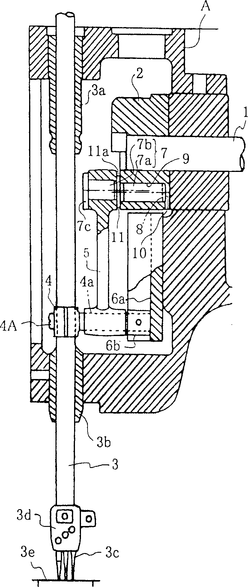
[0011] Next, embodiments according to the present invention will be described based on the drawings. figure 1 It is a partial sectional view showing a part of the sewing machine according to the present invention. The upper shaft 1 is pivotally supported in the sewing machine head A substantially horizontally, and is linked with a driving motor (not shown) to rotate in the same direction. A needle bar crank 2 is installed on the top of the upper shaft 1 . A needle bar 3 that can slide is arranged in the sheaths 3a, 3b fixed up and down in the sewing machine head A. The needle 3c is mounted on a needle clamp 3d fixed to the lower end of the needle bar 3, and passes through a needle plate 3e provided on the sewing machine table (not shown) when the needle bar 3 descends. Install clamp 4 with screw 4A in the middle of needle bar 3. The jig 4 has a substantially horizontally extending shaft 4 a rotatably pivoting the link 5 . The top end of the shaft 4a is vertically slidably ...


PUM


Abstract

The utility model relates to a sewing machine needle bar stroke changing device which can change the needle bar stroke correctly and surely. The device is provided with a needle bar crank installed on the upper shaft, a connecting rod rotatably pivoted in the middle of the needle bar, and an eccentric embedded shaft on the left and right, which are respectively connected to the needle bar crank and the connecting rod. The eccentric pin changes the aforementioned needle bar stroke by changing the embedded state of the aforementioned needle bar crank and the aforementioned eccentric pin, and at least At the same time as a recess, a protrusion is provided on the hole of the aforementioned needle bar crank used to embed the eccentric pin. When changing the stroke of the needle bar, the eccentric pin slides axially from the needle bar crank and rotates 180°. Refit the recess and the protrusion of the needle bar crank.

Description

technical field [0001] The invention relates to a device for changing the stroke of a needle bar which is linked with the upper shaft of a sewing machine and moves up and down. Background technique [0002] As disclosed in Japanese Patent Publication No. 63-57078, this sewing machine is provided with a needle bar crank mounted on an upper shaft, and a connecting rod rotatably pivoted at the middle of the needle bar, both of which are connected by an eccentric pin. The eccentric pins have their own eccentric embedded shafts on the left and right. One side of the left and right embedded shafts is inserted into the needle bar crank, and the other side is inserted into the connecting rod. The needle bar crank has a set screw for fixing the eccentric pin. The procedure for changing the needle bar stroke is as follows. Firstly, loosen the positioning screw of the needle bar crank, and secondly, rotate the eccentric pin relative to the needle bar crank in the circumferential dir...

Claims


Application Information

Patent Timeline
IPC IPC(8): D05B55/14
CPCD05B3/02D05B55/14
Inventor 山崎义启
Owner PEGASUS SEWING MACHINE MFG
Why Eureka
Try Eureka