Organic electroluminance display

A display device and electroluminescence technology, applied in electroluminescence light source, lighting device, light source, etc., can solve the problems of high manufacturing cost, increase manufacturing cost, weaken the competitiveness of organic electroluminescent display panel, etc.

Inactive Publication Date: 2003-02-19
LG ELECTRONICS INC
View PDF0 Cites 4 Cited by
  • Summary
  • Abstract
  • Description
  • Claims
  • Application Information

AI Technical Summary

Problems solved by technology

[0007] Therefore, the manufacturing cost is increased by adopting two FPCs (or TCPs) and performing the TAB process twice,

Method used


Image

  • Organic electroluminance display
  • Organic electroluminance display
  • Organic electroluminance display

Examples


Embodiment Construction

[0017] Reference will now be made in detail to the preferred embodiments of the present invention, examples of which are illustrated in the accompanying drawings. Wherever possible, the same reference numbers have been used throughout the drawings to designate the same or like parts.

[0018] An organic electroluminescent display panel according to the present invention will be described with reference to the accompanying drawings.

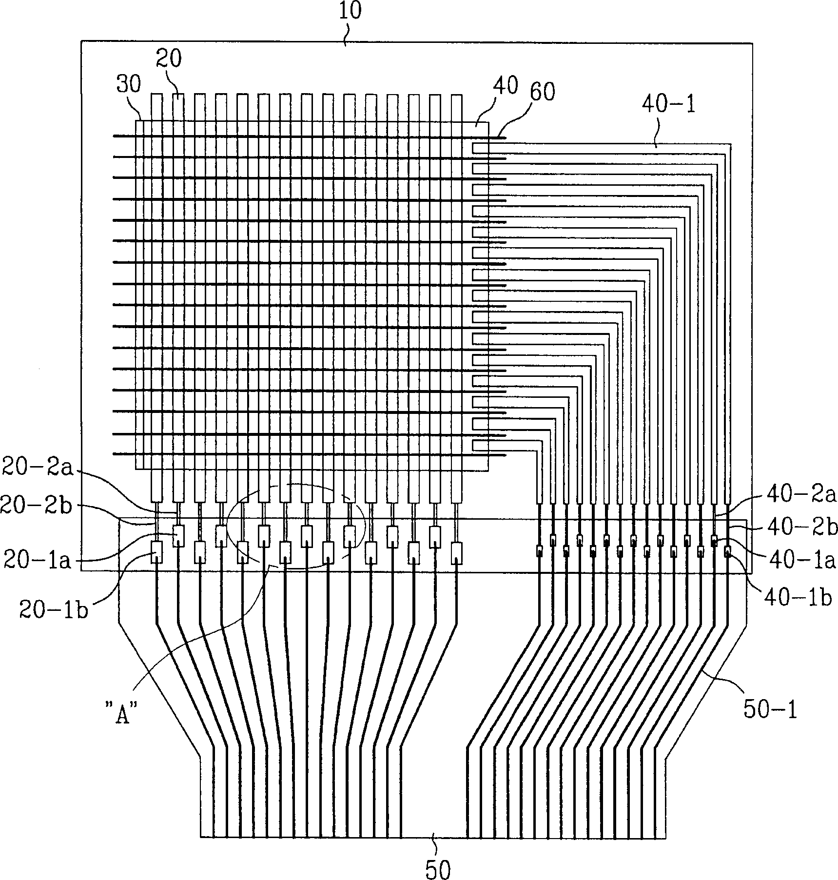
[0019] figure 2 is a plan view showing an organic electroluminescent display panel equipped with a thin film type device according to the present invention.

[0020] Such as figure 2 As shown, the organic electroluminescent display panel includes a transparent substrate 10, an organic electroluminescent layer 30, a connecting portion 40-1 of the second electrode, a shield 60, first electrode wires 20-2a, 20-2b and a second electrode Two electrode wires 40-2a, 40-2b.

[0021] At this time, the organic electroluminescence layer 30 is formed as...


PUM


Abstract

An organic EL display device is disclosed, which is fabricated in a tape automated bonding (TAB) method. The organic EL display device includes a driving part; a display panel including a substrate, a plurality of first and second electrodes formed on the substrate in a matrix type; and first and second lines having different lengths for being alternately arranged, and respectively applying signals from the driving part to the first and second electrodes; and a connecting part including a third line for electrically connecting the first and second lines to the driving part.

Description

technical field [0001] The present invention relates to a display device, and more particularly to an organic electroluminescence display device made by a tape automated bonding (TAB) method. Background technique [0002] figure 1 is a plan view showing an organic electroluminescence display panel equipped with a prior art film type device. [0003] Such as figure 1 As shown, the organic electroluminescent display device includes a first electrode 2 , a second electrode 4 , a connecting portion 4 - 1 of the second electrode, a shield 6 and an organic electroluminescent layer 3 . [0004] The strip electrodes are produced by chemical etching on the transparent substrate 1 , while the second electrodes 4 are formed perpendicularly to the first electrodes 2 . At this time, the connection portion 4-2 of the second electrode is used to easily form the second electrode pattern, and the shield is formed to electrically disconnect the second electrode pa...

Claims


Application Information

Patent Timeline
IPC IPC(8): H05B33/06H01L27/32H01L51/50
CPCH01L27/3288H10K59/179H05B33/06
Inventor 金昌男
Owner LG ELECTRONICS INC
Why Eureka
Try Eureka