Liquid crystal display device

A liquid crystal display device and substrate technology, which is applied in nonlinear optics, instruments, optics, etc., and can solve the problem that the cell gap cannot be consistent and the same.

Inactive Publication Date: 2003-03-05
JAPAN DISPLAY INC
View PDF3 Cites 52 Cited by
  • Summary
  • Abstract
  • Description
  • Claims
  • Application Information

AI Technical Summary

Problems solved by technology

[0015] However, even with the invention of JP-A-2001-21902, changing the thickness of the single layer of the above-mentioned resin constituting the spacer depending on the formation area still cannot make the above-mentioned cell gaps uniform enough, and in the process of implementing

Method used


Image

  • Liquid crystal display device
  • Liquid crystal display device
  • Liquid crystal display device

Examples


Embodiment Construction

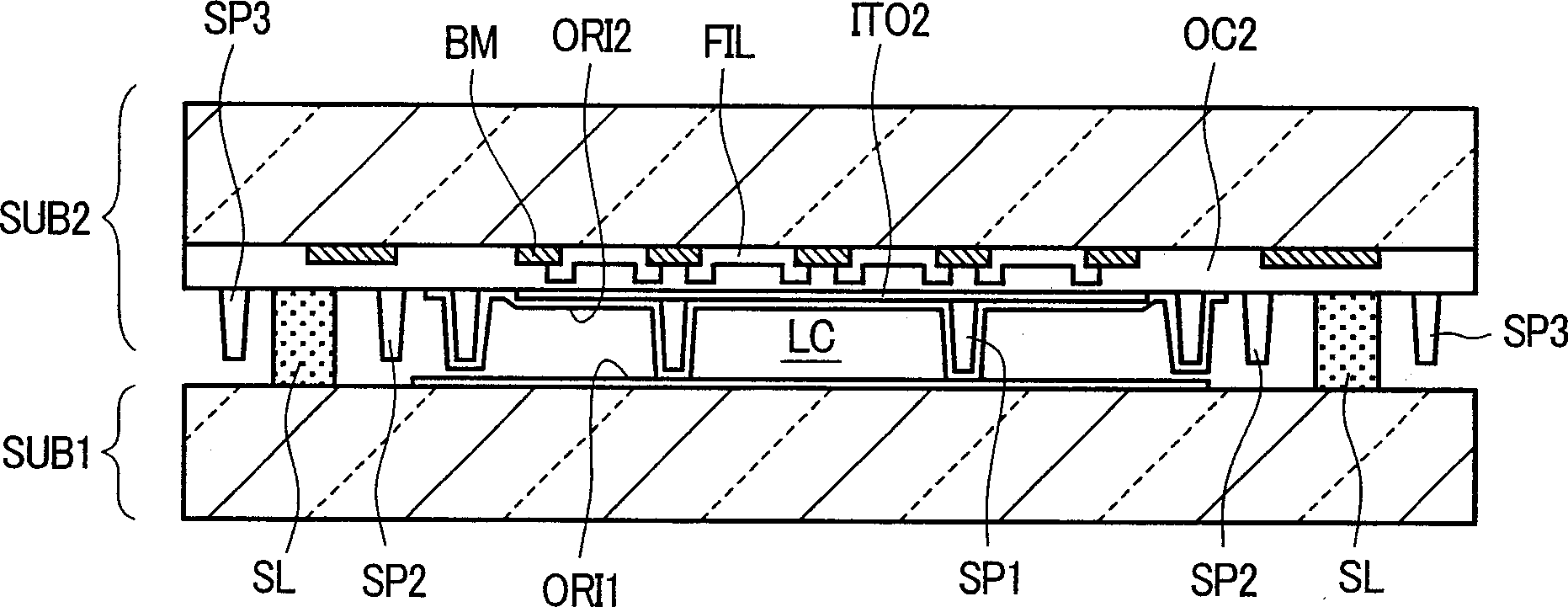
[0045] Hereinafter, the embodiment of the present invention will be described in detail with reference to the drawings of the embodiments. Here, a TN-type liquid crystal display device with a thin film transistor as a switching component is taken as an example for illustration.

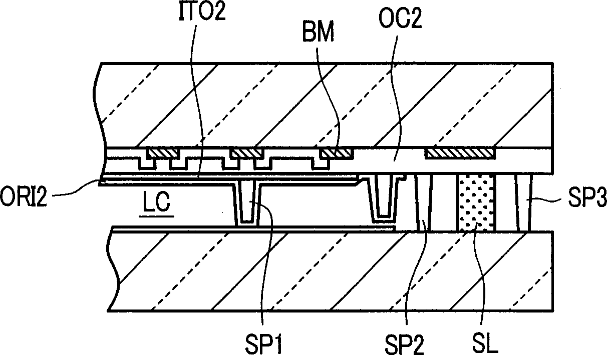
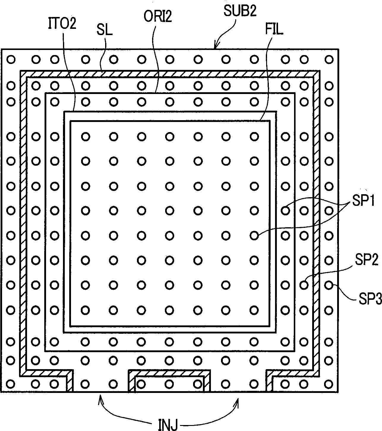
[0046] figure 1 It is a cross-sectional view of a liquid crystal display device for schematically explaining the first embodiment of the liquid crystal display device of the present invention. The figure shows the liquid crystal display device before pressure is applied in the thickness direction of the substrates in order to determine the gap between the two substrates sandwiching the liquid crystal layer, that is, to determine the so-called cell gap. In the figure, SUB1 is a thin film transistor substrate, and SUB2 is a color filter substrate. Although a plurality of thin film transistors are formed corresponding to pixels on the inner surface of the thin film transistor substrate SUB1, only the o...


PUM


Abstract

The present invention provides a liquid crystal display unit to prevent a shortcircuit between a common electrode on the side of a color filter substrate and a wiring and an electrode on the side of a thin film transistor and to set a precise cell gap in the entire area including the sealing area of two substrates. In which, columnar spacers SP1 are fixed in prescribed positions by forming the columnar spacers on the common electrode ITO2 and on a transparent protective film OC2 where the common electrode does not exist at the color filter substrate SUB2 and coating the columnar spacers on the common electrode with an alignment layer. Columnar spacers SP2 and SP3 are provided in the vicinity of the inner and the outer parts of a sealing area SL to secure the prescribed cell gap in the entire area of the two substrates and the sagging and to secure the height of the applied sealing material.

Description

technical field [0001] The present invention relates to a liquid crystal display device, and more particularly to a liquid crystal display device having a spacer of a new structure for maintaining a constant distance between a pair of substrates encapsulating liquid crystal. Background technique [0002] Liquid crystal display devices are widely used as display devices capable of high-definition and color display for notebook computers and computer monitors. In this type of liquid crystal display device, at least one side is basically formed of transparent glass or the like, and liquid crystal is sandwiched between a pair of opposing substrates. [0003] Liquid crystal display devices can be broadly classified into: a form in which voltages are selectively applied to various electrodes for forming pixels formed on a pair of substrates to turn on and off designated pixels (simple matrix liquid crystal display devices); Various electrodes on one or both of the above-mentioned...

Claims


Application Information

Patent Timeline
IPC IPC(8): G02F1/1339G02F1/1341G02F1/1362
CPCG02F1/13394G02F1/1362G02F2001/13396G02F1/13396G02F1/1339
Inventor 广岛实滨本辰雄山田广宣
Owner JAPAN DISPLAY INC
Why Eureka
Try Eureka