
Rotary bungalow

A technology of one-story houses and rotating shafts, which is applied to special buildings, small buildings, building types, etc., and can solve problems such as inconvenience

Inactive Publication Date: 2003-03-05
一弘企业株式会社
View PDF0 Cites 6 Cited by
  • Summary
  • Abstract
  • Description
  • Claims
  • Application Information

AI Technical Summary

Problems solved by technology

Therefore, users have to endure the pain of inconvenience, that is, have to use public kitchenettes, public toilets and public laboratories, etc.

Method used


Image

  • Rotary bungalow
  • Rotary bungalow
  • Rotary bungalow

Examples


Embodiment Construction

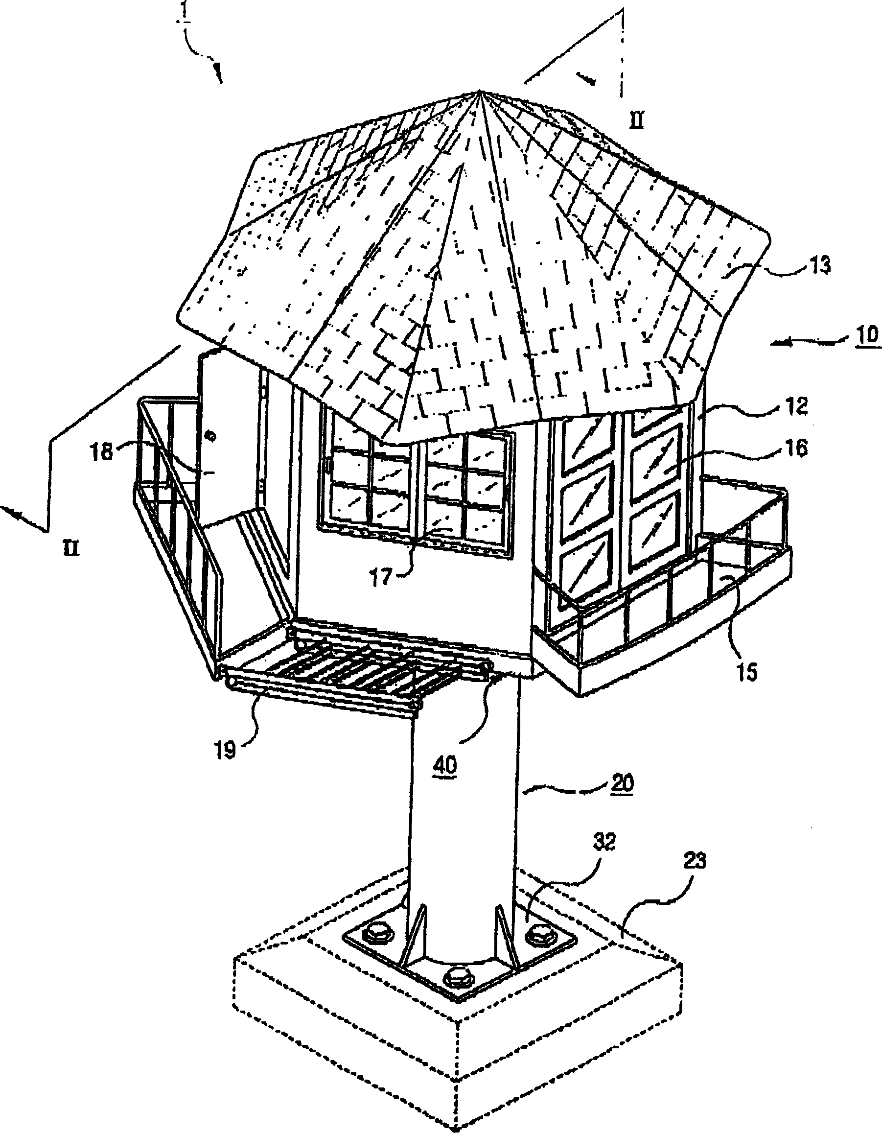
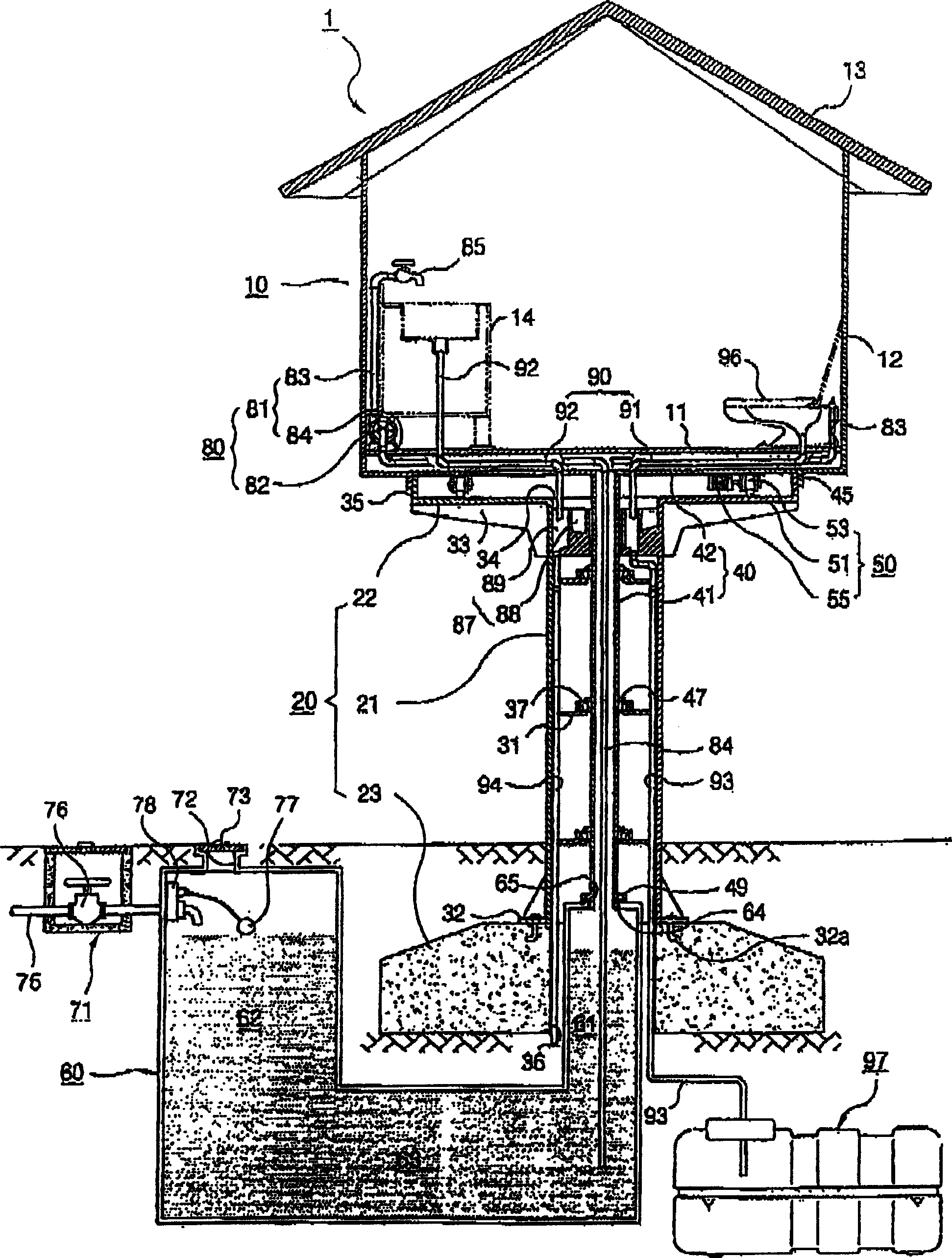
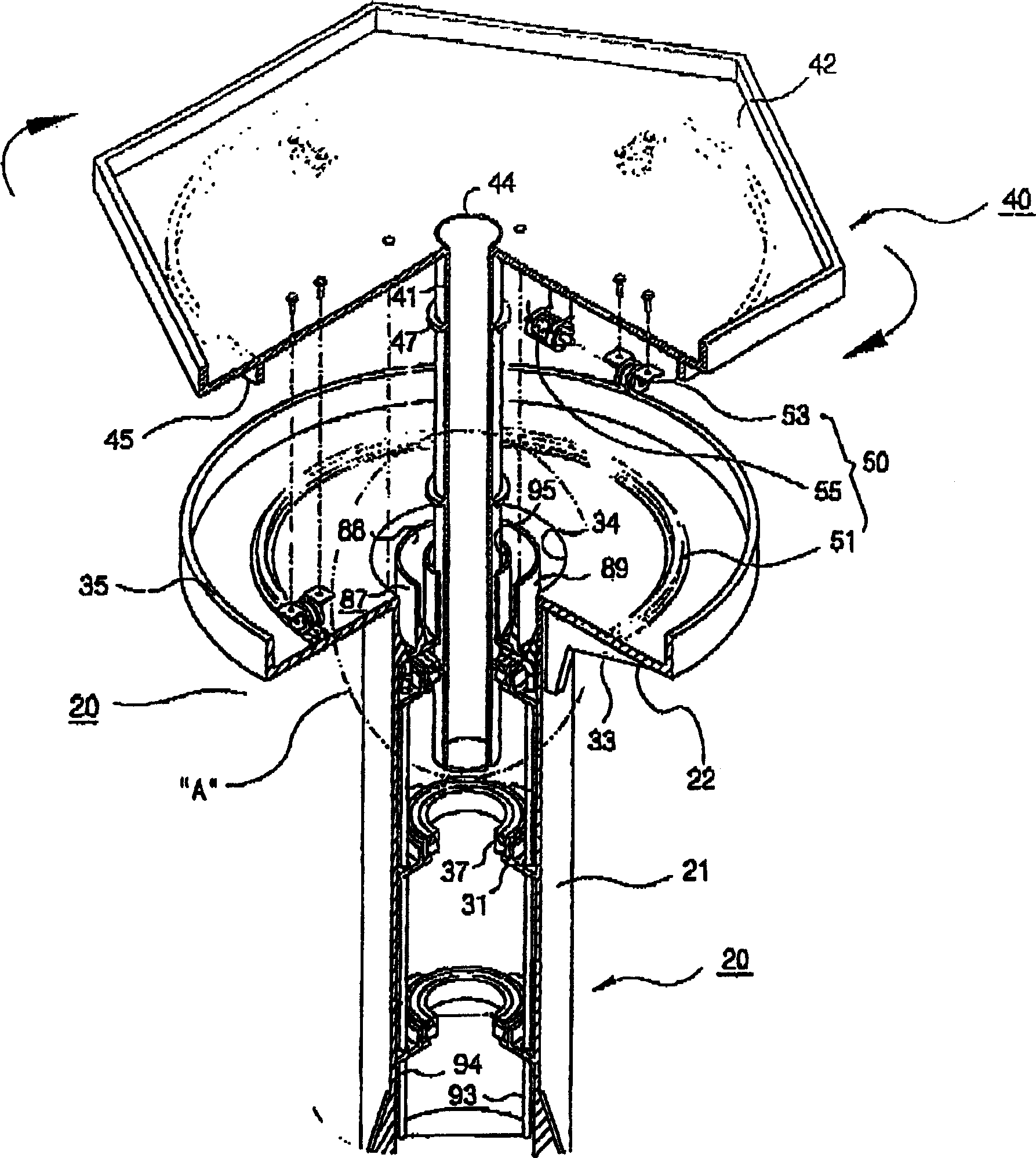
[0024] Please refer to Figure 1 to Figure 4 , a rotatable bungalow 1 in the present invention includes: a hut 10 providing indoor space; a supporting device 20, which raises the hut 10 from the ground to a predetermined distance; a rotating device 40, coupled to the bottom of the hut 10 , while being rotatably supported by the supporting device 20; a driving device 50 for rotating the rotating device 40; a water tank 60 installed under the hut 10; a water supply device 80 supplying water stored in the water tank 60 to the hut 10; and A drainage device 86 removes sewage generated in the hut 10 .

[0025] The hut 10 comprises: a polygonal bottom plate 11 to form the indoor ground; a plurality of wall members 12 are installed upright on each face of the bottom plate 11 to form the indoor space; and a roof member 18 to cover the top of the wall member 12 Open your mouth.

[0026] The floor 11, wall members 12 and roof members 13 together form the cabin 10 and are constructed of...


PUM


Abstract

Disclosed is a rotary bungalow, comprising a cabin forming an inner space therein; a hollow rotary shaft extended downward from the cabin; a support unit rotatably supporting the rotary shaft; a water tank installed under the cabin; a water pipe extended between the water tank and the cabin through the rotary shaft; and a water upmp drawing in the water within the water tank through the water pipe to the cabin. With this configuration, the user is allowed to use the rotary bungalow conveniently and pleasantly.

Description

technical field [0001] The invention relates to a rotatable bungalow. Background technique [0002] In general, flat houses are used in entertainment centers such as small rivers, mountains, beaches, etc., and provide places for tourists, climbers, etc. to rest or stay. The rotatable bungalows are able to rotate in a fixed area in order to meet the user's wishes, taking into account the view, the amount of sunlight or the wind direction. [0003] Please refer to FIG. 5 , which is a sectional view of an existing rotatable bungalow. The existing rotatable bungalow 101 includes a hut 110 for providing indoor space; a supporting device 120 for supporting the hut 110 to be lifted from the ground to a predetermined height; and a rotating device 150 for rotating the hut 110 . [0004] Rotary hut 110 comprises a rectangular plate member 111 to form the bottom; A plurality of wall members 112 are installed on the side of the plate member 111 upright to form an indoor space; Live i...

Claims


Application Information

Patent Timeline
IPC IPC(8): E04B1/00E04B1/346E04H1/12
CPCE04B2001/0092E04B1/3465E04H1/1205
Inventor 朴柄基
Owner 一弘企业株式会社
Learn More