Manhole cover assembly

A component and manhole cover technology, applied in water conservancy projects, artificial islands, underwater structures, etc., can solve the problems of large force at the junction, troublesome operation, difficulties, etc., to facilitate manufacturing and on-site installation, avoid well seat displacement, The effect of solving the settlement problem

Inactive Publication Date: 2003-03-26
BEIJING SIFANGRUGANG CONCRETE PROD
View PDF7 Cites 7 Cited by
  • Summary
  • Abstract
  • Description
  • Claims
  • Application Information

AI Technical Summary

Problems solved by technology

However, the technical scheme disclosed in CN2400503Y is due to adopting a connecting rod to be hingedly connected with the well cover plate and the well ring seat respectively, so its stability is poor, especially when opening and closing the well cover plate, the well cover plate needs to move as a whole, and the well cover plate cannot be The edge is used as a support point, which brings a lot of trouble and difficulty to the staff to carry out the operation
At the same time, the junction point has to bear a large force, especially the shear stress on the hinge between the connecting rod and the ring seat makes the hinge very easy to damage
And though the technical solution disclosed in CN2392818Y structurally solves the various defects in the above-mentioned technical solution, because it adopts the connection mode of multiple hinges, it needs multiple riveting when making and producing such a well cover assembly, and In order to ensure the stability of the manhole cover plate when it is opened and closed, the connecting rods in the inner hinge must be symmetrically arranged or the size of the parts must be increased, which will make the structure complicated or the shape of the upper part stupid, and multiple hinges are working together. It is easy to interfere with each other, and if it is not handled properly at this time, it will cause damage to the components

Method used


Image

  • Manhole cover assembly
  • Manhole cover assembly
  • Manhole cover assembly

Examples


Embodiment Construction

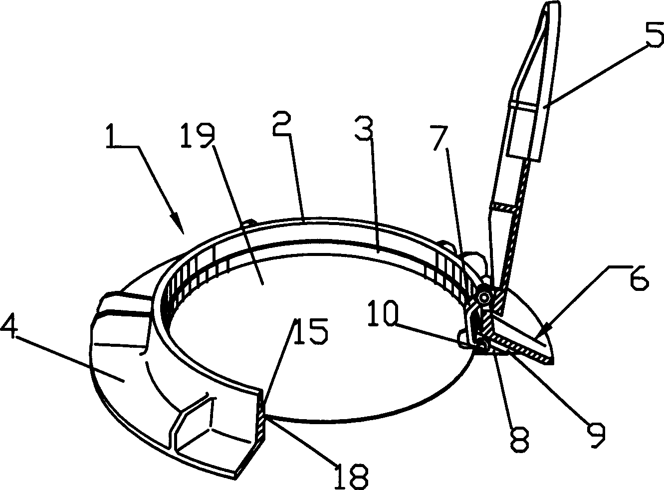
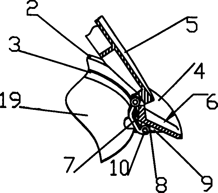
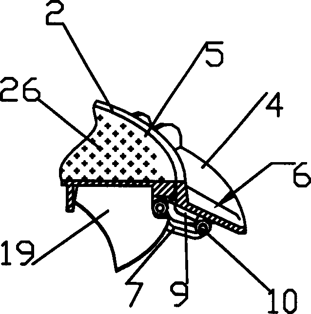
[0032] figure 1 Shown is the first embodiment of the present invention, wherein the manhole cover assembly of the present invention comprises a well circle seat 1, has on said well circle seat 1 an annular well circle seat outer ring opening 2 whose axis is substantially perpendicular to the ground , the manhole cover support platform 3 that protrudes radially inward from the inner wall of the outer ring mouth 2 of the well ring seat substantially perpendicular to its axis and extends radially outward from the lower edge of the outer ring mouth 2 of the well ring seat and a manhole cover 5 matched with the manhole cover support platform 3 and the outer ring mouth of the well ring seat; a slideway structure 6 is set below the manhole cover support platform 3, and a connecting One end of the rod 7 is limited in the slideway structure 6 and can slide therein, and the other end of the connecting rod 7 is hinged to the well cover plate 5 . The connecting rod 7 has an arcuate shape...


PUM


Abstract

THe invention refers to a well-cover component. It comprises a well ring stand on which is there an external ring mouth, support platform and external fixing board; a well-covering board; there is a slide structure set under the support platform and one end of connecting rod is limited in the slide structure and can slide in it and the other end is hinged with the well-covering board. It is especially applied to the well covers of all kinds of wells on the road establishment.

Description

technical field [0001] The invention relates to a well cover assembly. Specifically, the present invention provides a well cover assembly in which a well cover plate and a well ring seat are connected as one in a permanently connected manner. Background technique [0002] Usually, the manhole cover plates of various wellheads on the road are directly covered on the well ring seat, and there is no connection between the manhole cover plate and the well ring seat. The ring seat loses the assembly relationship, and even flies away from the well ring seat, causing the wellhead to be covered, which seriously affects the safety of pedestrians and vehicles. [0003] In order to solve this problem, people have proposed the technical scheme of locking between the well cover plate inboard and the well ring seat, although such a scheme can solve the above problems. However, corresponding keys must be used to open the well cover, which brings a certain burden to the relevant personnel...

Claims


Application Information

Patent Timeline
Patent Type & Authority Applications(China)
IPC IPC(8): E02D29/14E04F19/08
Inventor 梁林华
Owner BEIJING SIFANGRUGANG CONCRETE PROD
Why Eureka
Try Eureka