Bourdon tubular gauge

A Bourdon tube and pressure gauge technology, applied in the direction of elastic deformation gauge type fluid pressure measurement, etc., can solve complex problems

Inactive Publication Date: 2003-04-09
FUJI BOURDON TUBULAR GAUGE
View PDF0 Cites 3 Cited by
  • Summary
  • Abstract
  • Description
  • Claims
  • Application Information

AI Technical Summary

Problems solved by technology

Therefore, in this case, it is necessary to repeat several complicated operations until the zero scale and the maximum scale are aligned.

Method used


Image

  • Bourdon tubular gauge
  • Bourdon tubular gauge
  • Bourdon tubular gauge

Examples


Embodiment Construction

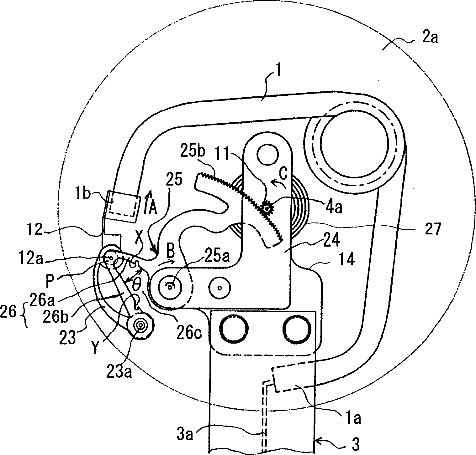
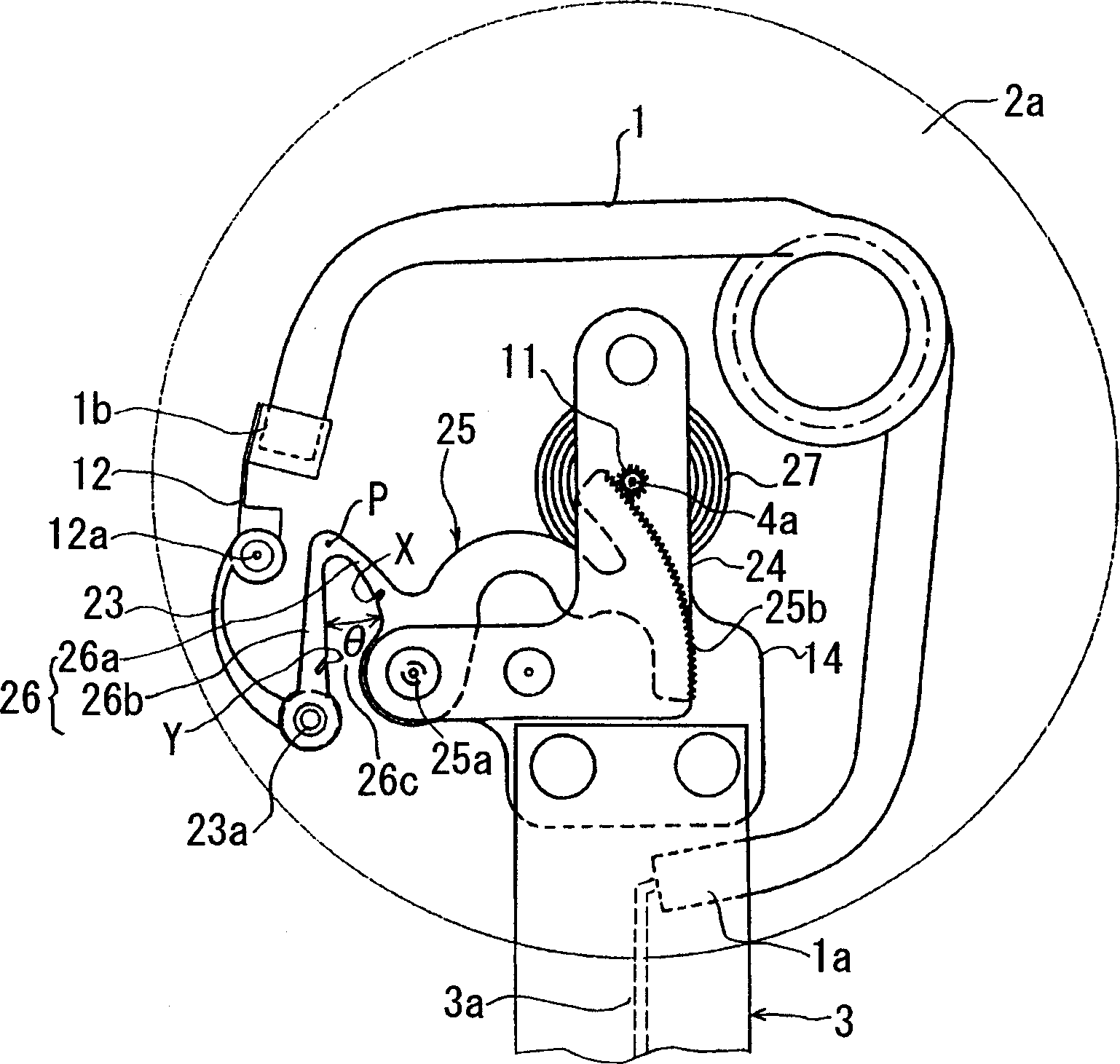
[0021] An embodiment of the present invention will be described below with reference to the accompanying drawings. figure 1 It is a rear view showing the displacement expansion link mechanism in the state where the maximum pressure is applied in the Bourdon tube pressure gauge related to the embodiment of the present invention, figure 2 It is a rear view showing the displacement expansion link mechanism in a pressureless state in the Bourdon tube pressure gauge related to the embodiment of the present invention. In addition, in figure 1 , 2 in, with Figure 4 The parts shown in are the same parts with reference symbols, and their explanations are omitted.

[0022] The displacement expansion link mechanism of this example has a Bourdon tube 1, a bow-shaped connecting rod 23, and a rotating plate (lever arm, sector) 25, and the Bourdon tube 1 moves around the pointer shaft 4a at the tube end 1b as the pressure increases. 3-way with respect to the pressure inlet pipe as a ...


PUM


Abstract

To provide a Bourdon tube pressure gage capable of preventing a pointer from becoming out of order greatly from zero graduation even if it is returned into a non-pressure condition after attaching the pointer to a pointer shaft in the non-pressure condition while the pointer agrees with the zero graduation and making the pointer agree with the maximum graduation by plastically deforming a plastically bent arm part of a displacement enlargement mechanism in the maximum pressure applied condition to greatly improve the efficiency of the work for setting to graduation and calibration. In this Bourdon tube pressure gage, the displacement enlargement link mechanism is composed of a protruding piece (12) attached to a tube tip (1b), a bow-shaped articulated link (23), and a rotary plate (25). A V-shaped arm piece (26) as an adjusting piece in the maximum pressure applied condition in the rotary plate (25) is used, and a bendable nodal point P is provided as a position where it is overlapped on a first turn kinematic pair part (12a) of the protruding piece (12) and the bow-shaped articulated link (23) in the non- pressure condition.

Description

technical field [0001] The present invention relates to a Bourdon tube pressure gauge, and in particular to an improvement of a scale alignment adjusting member in a displacement enlarging mechanism for enlarging the displacement of the tube end of the Bourdon tube pressure gauge and transmitting it to the pointer shaft. Background technique [0002] The schematic configuration of a Bourdon tube pressure gauge that mechanically expands and expresses the elastic deformation of metal produced by the measured pressure is as follows image 3 As shown, it is composed of a watch main body 2 and a pressure introduction tube 3 with a male screw part 5b. The watch main body 2 is a Bourdon tube with an elliptical cross-section, for example, bent and accommodated in a circular flat cylindrical shape. The pressure introduction tube 3 is connected to the pressure source to be measured through the communication hole 5a. The installation hole (screw hole) 5 with the female screw part 5b on ...

Claims


Application Information

Patent Timeline
Patent Type & Authority Applications(China)
IPC IPC(8): G01L7/04
Inventor 宫坂晖朗
Owner FUJI BOURDON TUBULAR GAUGE
Why Eureka
Try Eureka