Hand vibrating tool

A technology of hand-held tools and vibrating hands, which is applied in the direction of manufacturing tools, metal processing equipment, portable grinding beds, etc., and can solve the problem that sand tiles cannot rotate freely.

Inactive Publication Date: 2003-04-30
BLACK & DECKER INC
View PDF2 Cites 7 Cited by
  • Summary
  • Abstract
  • Description
  • Claims
  • Application Information

AI Technical Summary

Problems solved by technology

Therefore, in this orbital grinder, the sandstone cannot rotate freely about its axis

Method used


Image

  • Hand vibrating tool
  • Hand vibrating tool
  • Hand vibrating tool

Examples


Embodiment Construction

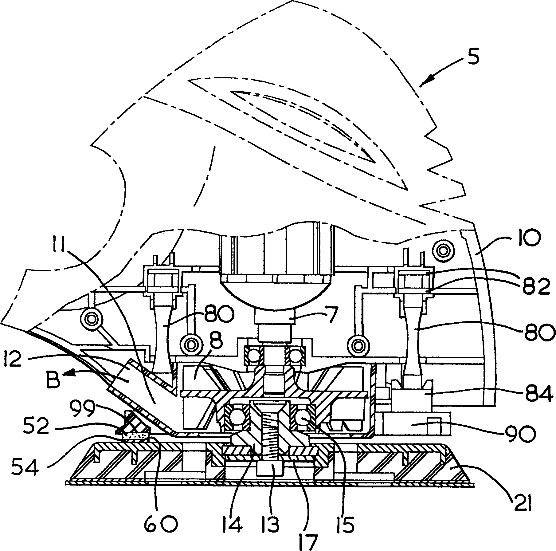
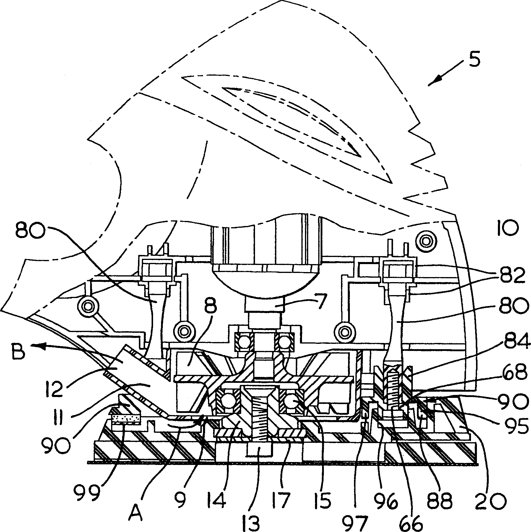
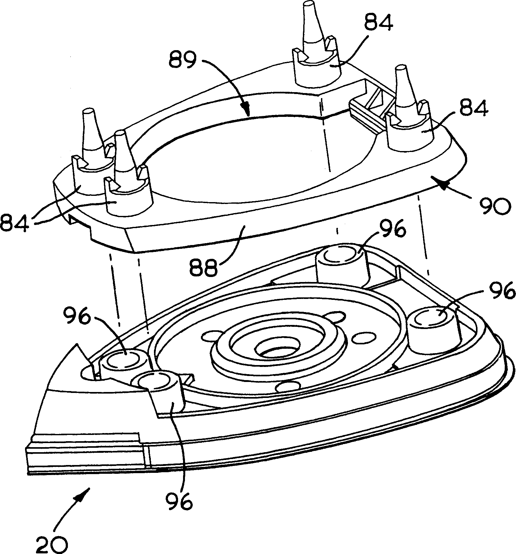
[0036] Embodiments of the invention are described by way of example with reference to the accompanying drawings. figure 1 A drive element 5 is shown, comprising an electric motor (not shown) and a first drive shaft 7 . A fan 8 mounted on the shaft 7 is arranged to suck air from the mouth 9 of the drive element 5 as indicated by arrow A and direct it through the extraction duct 11 into the outlet 12 as indicated by arrow B. The bearing 15 is arranged radially eccentrically with respect to the shaft 7 , and the second drive shaft 14 rotates around the axis of the bearing 15 . The installation platform 90 is fixed to the casing 10 by means of four elastic rubber brackets 80 . The mounting platen 90 is substantially flat, and the brackets 80 extend from a common major surface of the mounting platen 90 (the upper surface as shown in the figures), which leads into the body of the housing 10 . Resilient brackets 80 extending from mounting platen 90 are permanently affixed to housin...


PUM


Abstract

The powered oscillating hand tool is provided having a first drive shaft 7 and a bearing 15 mounted eccentrically relative to the first drive shaft 7. A second drive shaft 14 carries a mounting platen 90 by means of one or more flexible legs 80. The first and second platens are interchangeably mountable on the second drive shaft 14 and a brake means is provided on the mounting platen 90 to restrain the speed of rotation of a selected first or second platen.

Description

technical field [0001] The present invention relates to a power driven vibrating hand tool, and more particularly to a power driven vibrating hand tool with an interchangeable sanding plate attachment. Background technique [0002] Vibrating hand tools with abrasive attachments are known. Known abrasives are often orbital abrasives or irregular orbital abrasives, or a combination of both in one hand tool. [0003] Orbital abrasives typically include a shaped sand shoe whose drive system has eccentric motion that is so limited that the sand shoe cannot rotate independently of the motor. Therefore, in such an orbital grinder, the sandstone cannot rotate freely about its axis. The sanding tiles of this orbital grinder are typically used to remove relatively small quantities of material, such as for finishing or finishing. Additionally, sand tiles can be shaped to access difficult corners etc. and can be used to remove any material in these locations. [0004] In contrast, i...

Claims


Application Information

Patent Timeline
Patent Type & Authority Applications(China)
IPC IPC(8): B24B23/04
CPCB24B23/04
Inventor 安德鲁·沃克
Owner BLACK & DECKER INC
Why Eureka
Try Eureka