Eureka AIR delivers breakthrough ideas for toughest innovation challenges, trusted by R&D personnel around the world.

Inhaling holding device

A technology for holding device and air, applied in electrical components, transportation and packaging, furnaces, etc., can solve the problems of wafer W prone to cracks and damages

Inactive Publication Date: 2003-06-11
LINTEC CORP
View PDF1 Cites 5 Cited by
  • Summary
  • Abstract
  • Description
  • Claims
  • Application Information

AI Technical Summary

Problems solved by technology

In particular, recent wafers W are ultra-thin in thicknesses of approximately 100 μm to 30 μm compared with conventional wafers having a thickness of approximately 350 μm to 200 μm, and such extremely thin wafers W have a disadvantage that when bowing occurs, When deformed, cracks or damage tend to easily occur on the wafer W

Method used


Image

  • Inhaling holding device
  • Inhaling holding device
  • Inhaling holding device

Examples


Embodiment Construction

[0023] Embodiments of the present invention will be described below with reference to the drawings.

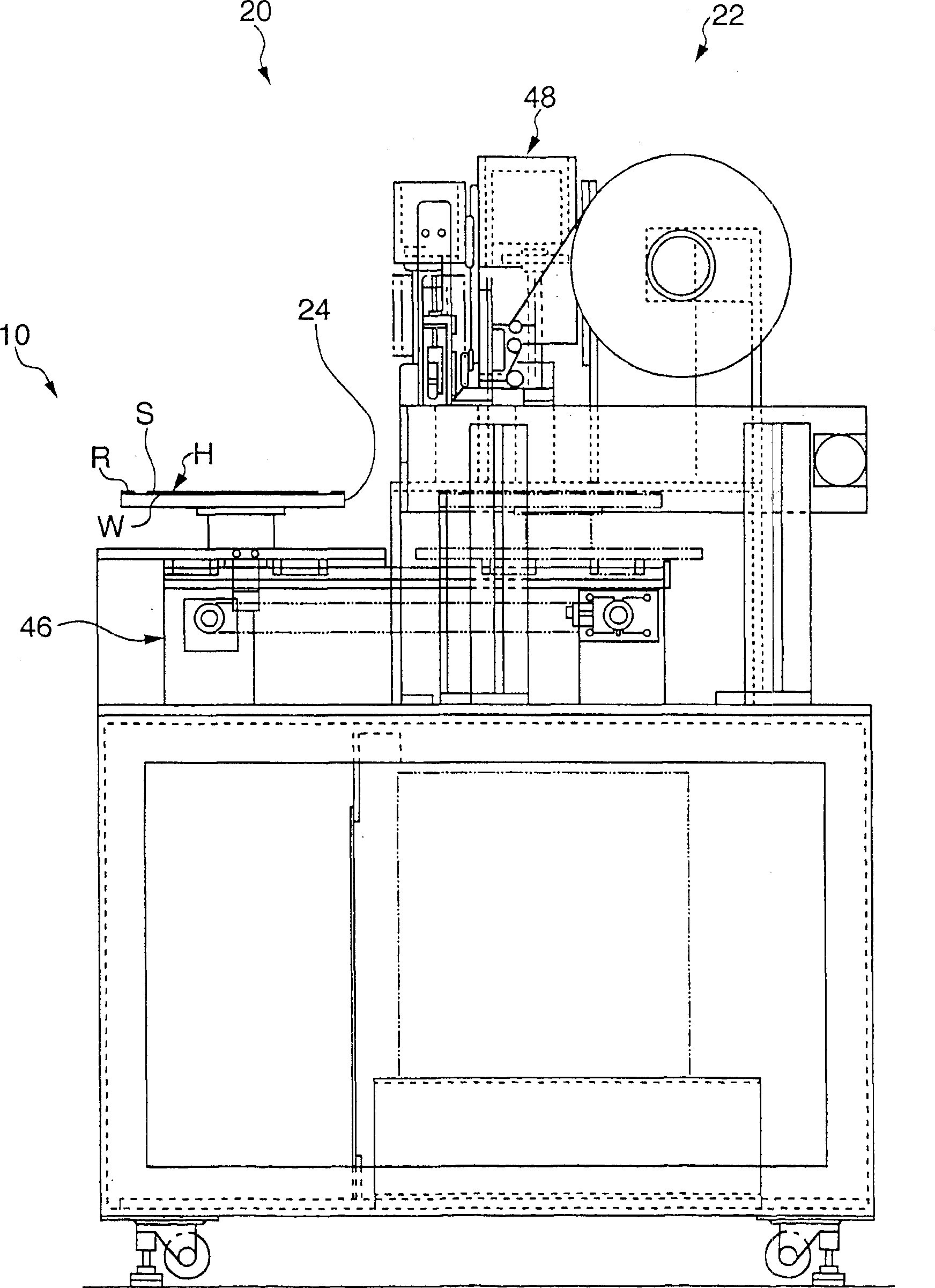
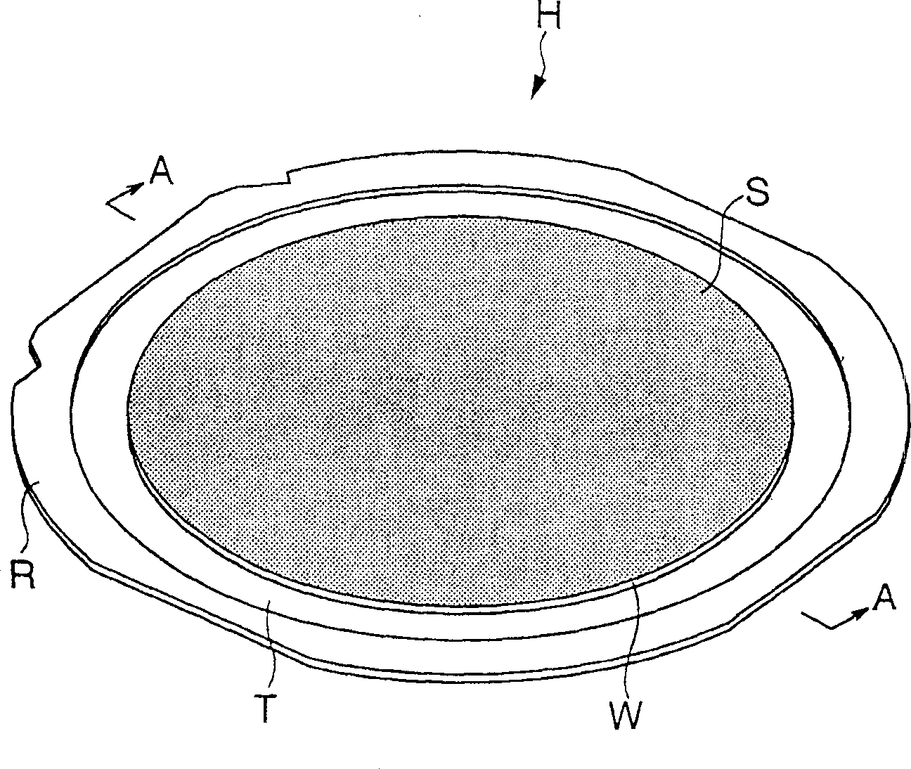
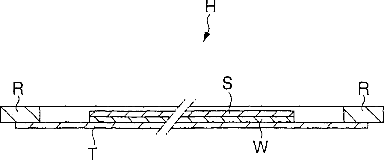
[0024] exist figure 1 , shows a schematic side view of a stripping device 20 to which a suction holding device 10 according to the invention is added. exist figure 2 , a schematic perspective view of a wafer holding device H as an object to be applied to the stripping device 20 is shown. exist image 3 in, showing figure 2 An enlarged vertical section view of . In these figures, the wafer holding device H comprises a generally disk-shaped wafer W, a protective layer S, a dicing tape T, and an annular frame R, the front (upper side) of the above-mentioned disk-shaped wafer W constituting a A circuit surface, a protective layer S is laminated on the circuit surface of the wafer W, a dicing tape T is bonded on the back surface of the wafer W, and a ring frame R is bonded along the peripheral portion of the dicing tape T.

[0025] The stripping device 20 is a device for au...


PUM


Abstract

A suction holding device 10 comprises a table 24 on which a wafer holder H is mounted, and suction side conduits 25 connected to the table 24. The table 24 includes a suction plane 28 provided with a plurality of suction holes 27 on its upper side, and a chamber 32 in fluid communication with the suction holes 27. The chamber 32 is arranged such that it is divided into a plurality of cells 37, 38 and 39 each isolated from others, and that, when the wafer holder H is removed from the suction plane 28, air is independently supplied to respective cells 37-39, from the outer side of the table 24 toward the inner side in order.

Description

technical field [0001] The present invention relates to a suction holding device, and more particularly, to a suction holding device which prevents bowing of an object when the object is removed from a suction plane. Background technique [0002] Conventionally, there is known a peeling device for automatically peeling off a protective layer laminated on the front side constituting the circuit surface of a generally disc-shaped semiconductor wafer (hereinafter simply referred to as "wafer"). The peeling device is constructed such that the wafer holding device including a wafer is sucked and held by a suction holding device, the back side of the wafer is bonded to a dicing tape exposed inside a ring frame, in this Peel off the protective layer in the state, and then hold the wafer holding device to take it out from the side of the suction holding device. [0003] As for the suction holding device, a suction holding device 70 is known. For example, as shown in FIG. The wafer...

Claims


Application Information

Patent Timeline
Patent Type & Authority Applications(China)
IPC IPC(8): B25J15/06H01L21/00H01L21/301H01L21/683
CPCH01L21/67132H01L21/6838H01L21/30
Inventor 黑川秀二
Owner LINTEC CORP
Why Eureka
Eureka Blog
Learn More