Optical-driver tray locking device

A technology for locking devices and pallets, which is applied to instruments, structural components of record carriers, data recording, etc., and can solve problems such as power consumption

Inactive Publication Date: 2003-06-11
SAMSUNG ELECTRONICS CO LTD
View PDF1 Cites 10 Cited by
  • Summary
  • Abstract
  • Description
  • Claims
  • Application Information

AI Technical Summary

Problems solved by technology

[0009] However, in the tray locking device having the above structure, since current is continuously applied to the winding 61 to generate an electromagnetic force that cancels the attract

Method used


Image

  • Optical-driver tray locking device
  • Optical-driver tray locking device
  • Optical-driver tray locking device

Examples


Embodiment Construction

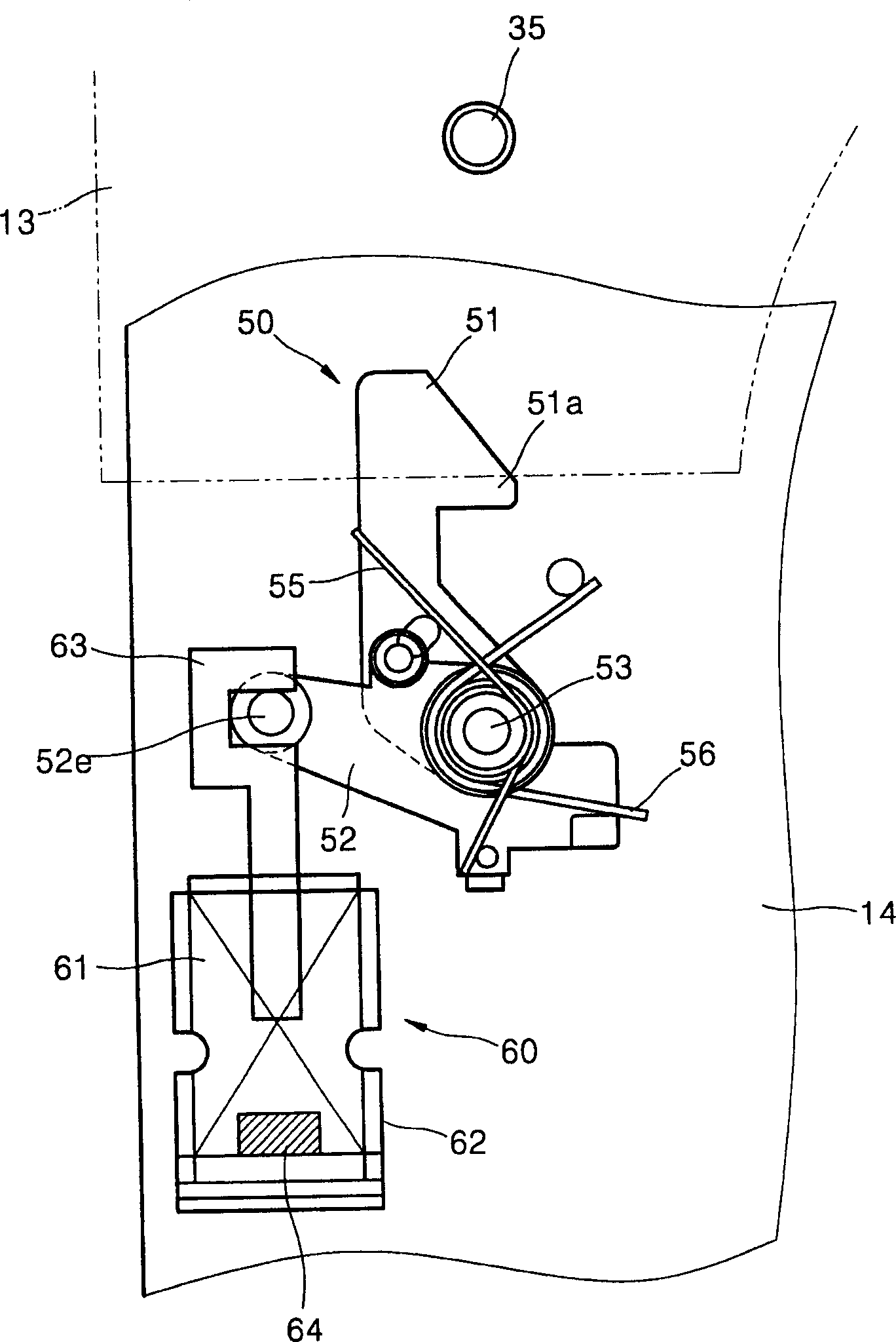
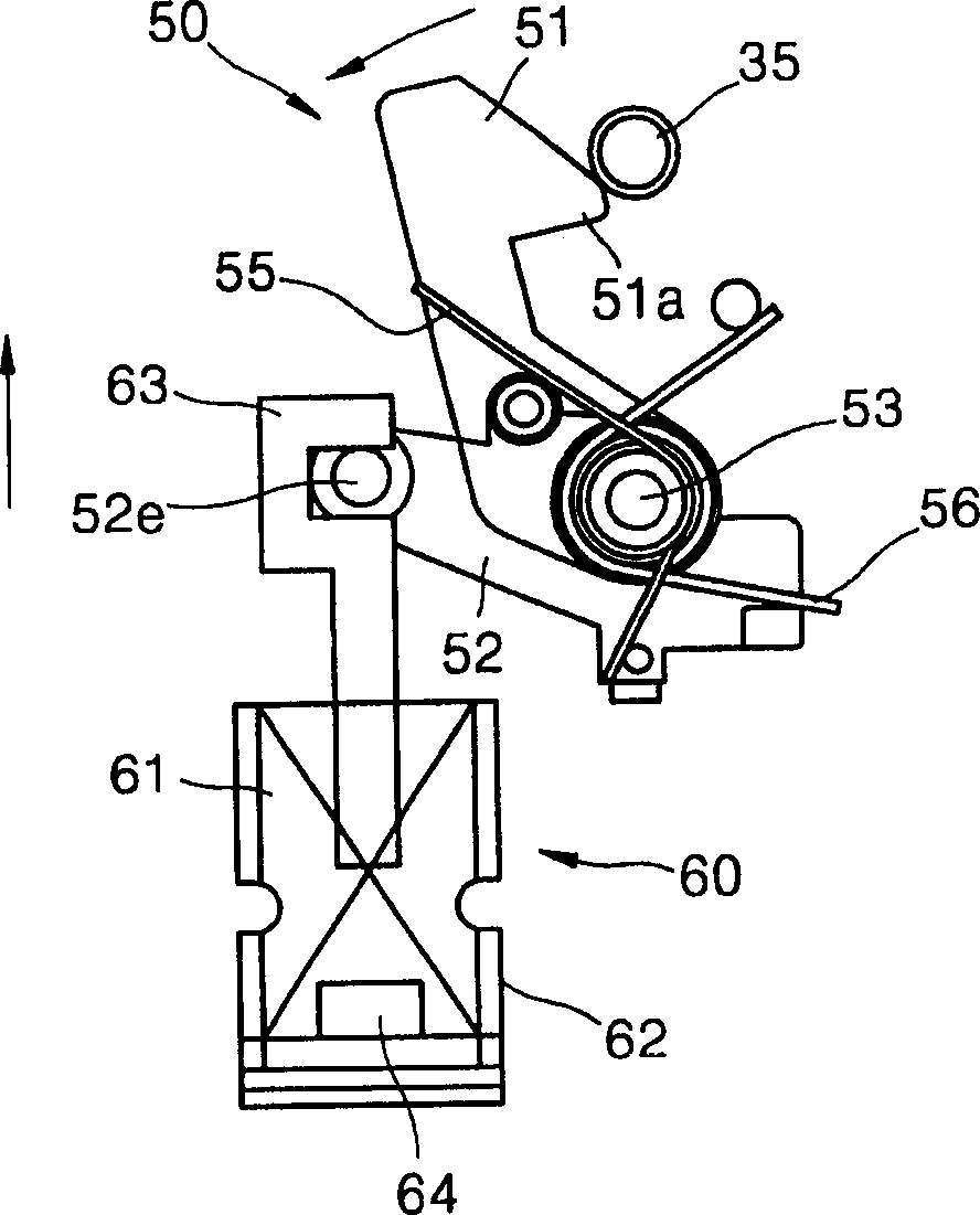
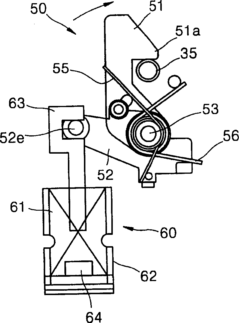
[0020] Figures 3 to 7 One side of the tray is shown, on which the locking device according to the first embodiment of the invention is mounted. refer to image 3 , the locking post 301 of the locking tray 100 is disposed on the main body 300 of the optical drive. The bracket 160 is fixedly installed on the bottom surface of the tray 100 by the connecting piece 161 . The locking plate 110 has a locking portion 111 caught by the locking post 301 when it enters the main body 300 , and the locking plate 110 is supported by the guide post 101 to be slidable relative to the bracket 160 . The spring 115 elastically biases the locking plate 110 in the direction in which the locking portion 111 is held by the locking post 301 , that is, to the right in the figure. Reference numeral 120 denotes a manual opening lever, which can be rotated around a rotating shaft 123 provided on the bracket 160 when installed, one end 121 of which is connected to the locking plate 110, and the other ...


PUM


Abstract

A tray locking apparatus of a disc drive to lock a tray on which a disc is placed and which is inserted into a main body of a disc drive. The tray locking apparatus includes a locking boss provided at the main body, a locking plate installed at the tray to slide and having a locking portion provided at one side thereof which is caught by the locking boss as the tray enters the main body, an elastic member to elastically bias the locking plate in a direction in which the locking portion is caught by the locking boss, and a driving mechanism to make the locking plate slide to be out of a position where the locking portion is caught by the locking boss when the tray is drawn. Thus, even when an external impact is applied, the locking state can be firmly maintained. Also, electric power consumed for the locking and unlocking operations is reduced.

Description

technical field [0001] The invention relates to an optical drive tray locking device for locking a tray inserted into an optical drive and opening the tray to eject the tray. Background technique [0002] In common optical drives that use optical discs as recording media, there is a tray for loading the optical disc into the optical drive, that is, when the optical disc is placed on the tray and inserted into the optical drive, the optical disc is loaded into the mounting position in the optical drive, and then recording can be performed on the optical disc and / or copy operations. Because the optical disc is not allowed to be ejected during recording and / or duplication, a tray locking position for locking the tray is provided in the optical drive. [0003] figure 1 The structure of the tray locking device disclosed in Japanese Patent Publication No. 2000-11513 is shown. As shown in the figure, the tray locking device includes: a locking pin 35 ar...

Claims


Application Information

Patent Timeline
IPC IPC(8): G11B33/02G11B17/04G11B17/056G11B33/08
CPCG11B17/047G11B33/08G11B17/056G11B17/04
Inventor 裵炳泳崔彦进洪舜教
Owner SAMSUNG ELECTRONICS CO LTD
Why Eureka
Try Eureka