Fibre-optical fixator, fibre-optical adapter and fibre-optical process equipment with location device

A fixer and optical fiber technology, applied in the coupling of optical waveguides, instruments, optics, etc., can solve problems such as fiber breakage

Inactive Publication Date: 2003-07-16
THE FUJIKURA CABLE WORKS LTD
View PDF1 Cites 10 Cited by
  • Summary
  • Abstract
  • Description
  • Claims
  • Application Information

AI Technical Summary

Problems solved by technology

[0028] The adapter 90 of the optical fiber insertion type (see FIGS. 26 and 26B) has a disadvantage in that when the optical fiber 64 is inserted into the small hole, it is used for the contact of the end surface of the optical fiber 64 with its surrounding parts, so that fine dust is attached to the end surface of the optical fiber 64. superior
[0029] An adapter 100 of the split type (such as Figure 27A and 27B shown) has a disadvantage that when the fiber cannot be placed precisely on the intended part, the phenomenon of fiber breakage occurs

Method used


Image

  • Fibre-optical fixator, fibre-optical adapter and fibre-optical process equipment with location device
  • Fibre-optical fixator, fibre-optical adapter and fibre-optical process equipment with location device
  • Fibre-optical fixator, fibre-optical adapter and fibre-optical process equipment with location device

Examples


Embodiment Construction

[0076] best practice

[0077] Other features of the present invention will become clearer through the description of the following preferred embodiments, and the given preferred embodiments are used to explain the present invention rather than limit the present invention.

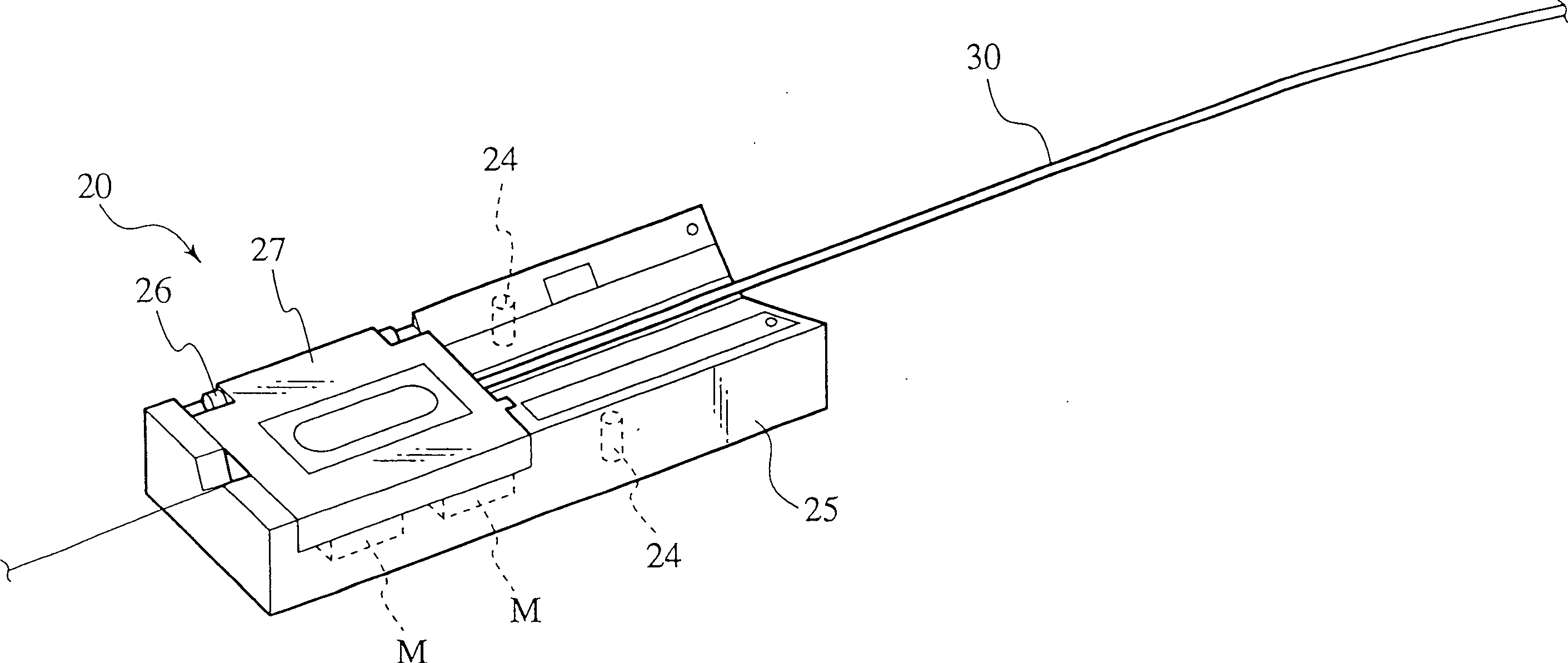
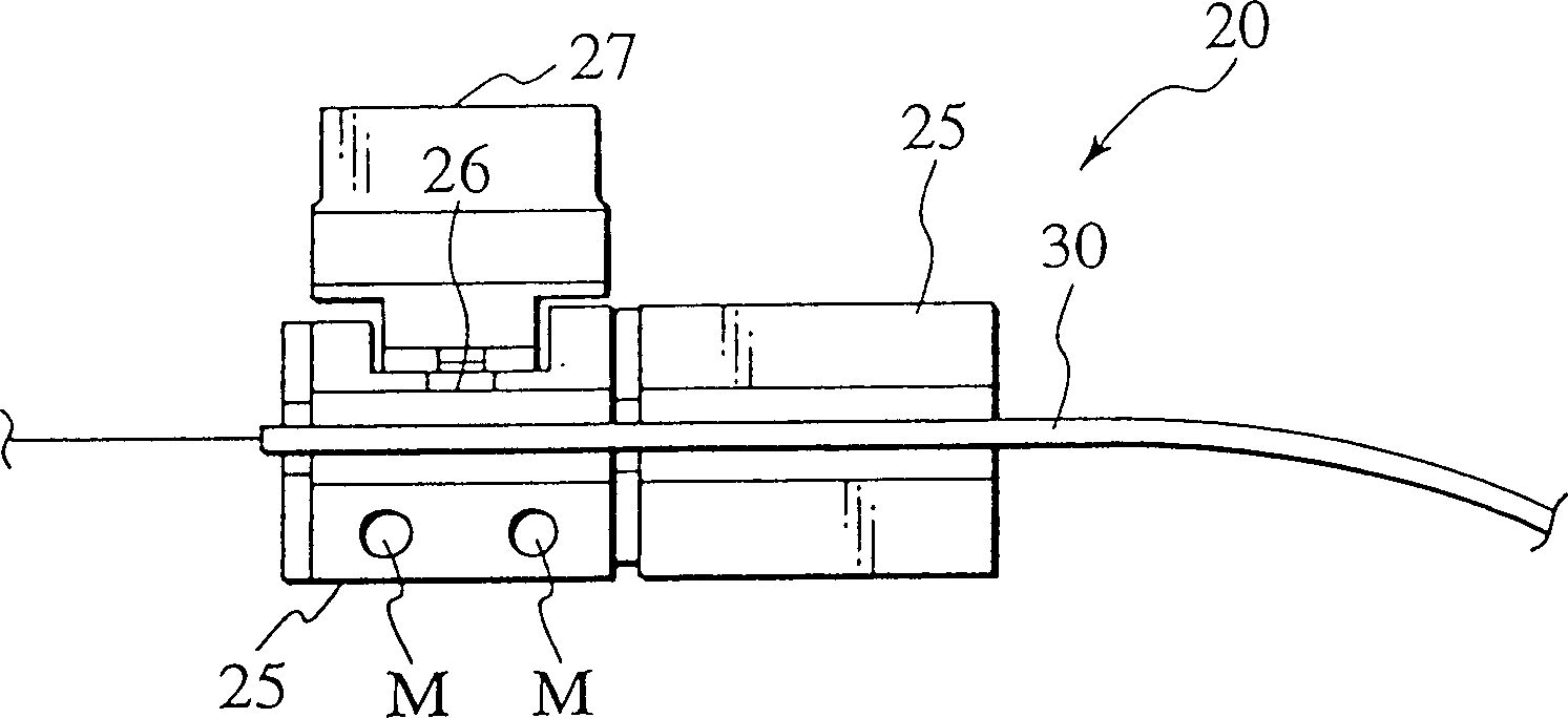
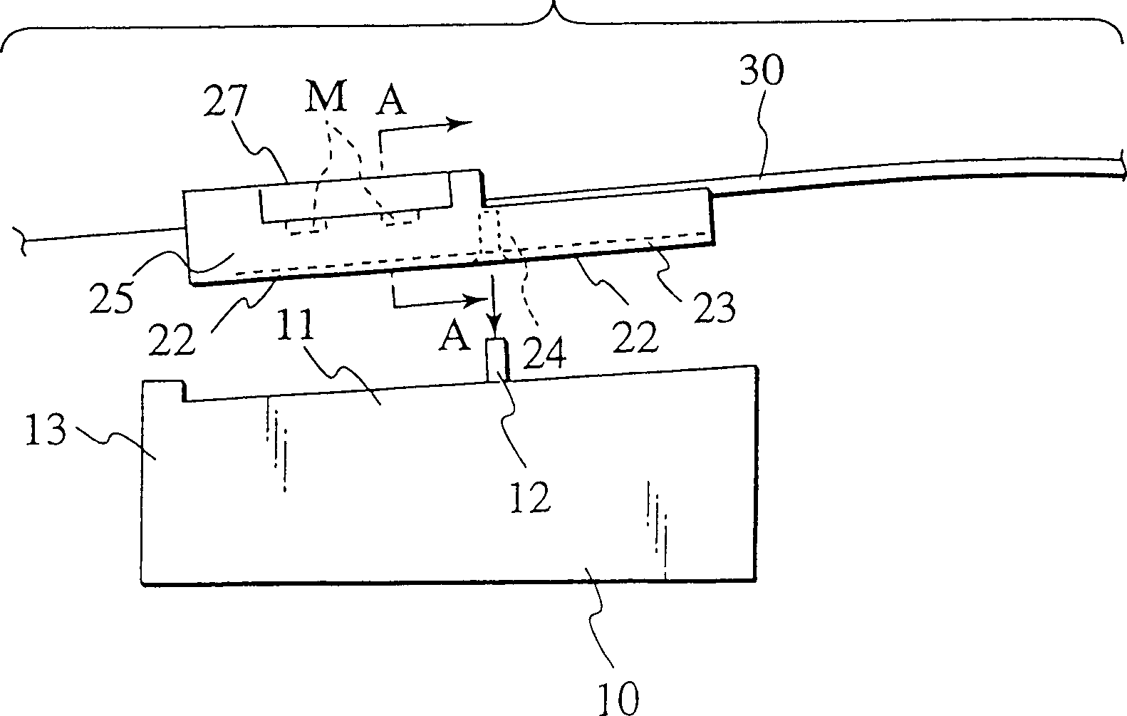
[0078] The fiber holder with a positioning mechanism, the fiber adapter with a positioning mechanism and the fiber processing device with a positioning mechanism will be described in detail below in conjunction with the accompanying drawings of the present invention. Subsequent descriptions show that the fiber holder of the present invention is fixed on various processing devices such as a fiber fuser, a high-strength shell stripper, a high-strength cutter, an ultrasonic cleaner, and the like. However, the present invention is not limited by these structures. For example, the fiber holder of the present invention can be applied to various fiber processing devices.

[0079] first embodiment

[0080] fig...


PUM


Abstract

Guiding rails (22) are formed along both the edge portions of a back surface (21) of an optical fiber holder (20), which guide positioning protrutions (12) formed on a mounting surface (110) in an optical fiber processing device (10). The interval between inner-wall surfaces (23) of the guiding rails (22) opposed to each other corresponds to the interval between the positioning protrutions (12). Hollow portions (24) are formed at the back surface (21) of the holder (20), into which the positioning protrutions (12) are inserted. The holder (20) is tightly fixed on the mounting surface (11) of the device (10).

Description

technical field [0001] The present invention relates to an optical fiber holder, an optical fiber adapter and an optical fiber processing device with a positioning mechanism, in particular to an optical fiber holder with a positioning mechanism for fixing optical fibers or optical fiber ribbons, and at the same time can easily and accurately set the optical fiber on the optical fiber adapter The invention relates to an optical fiber adapter with a positioning mechanism for fixing an optical fiber holder and is fixed in an optical fiber processing device. Background technique [0002] The application of the present invention is based on and requires that the prior Japanese patent application number is P2001-397008, the application date is December 27, 2001, the application number is P2002-060998, the application date is March 6, 2002; the application number is P3003-228934 , the priority of the Japanese patent application with the filing date of August 6. The entire content ...

Claims


Application Information

Patent Timeline
Patent Type & Authority Applications(China)
IPC IPC(8): B08B3/12B08B11/02G02B6/245G02B6/25G02B6/255G02B6/36G02B6/38
CPCG02B6/245B08B2240/02G02B6/3636B08B11/02G02B6/25B08B3/12G02B6/2551G02B6/2556G02B6/3616
Inventor 藤泽学高桥建次铃木纯一春木健一郎
Owner THE FUJIKURA CABLE WORKS LTD
Why Eureka
Try Eureka