Supercharge Your Innovation With Domain-Expert AI Agents!

Device for heat/moist exchange

An exchange equipment, heat and humidity technology, applied in the field of heat/humidity exchange equipment, can solve problems such as increasing pressure difference

Inactive Publication Date: 2003-07-23
斯万·梅尔克·尼尔松
View PDF0 Cites 6 Cited by
  • Summary
  • Abstract
  • Description
  • Claims
  • Application Information

AI Technical Summary

Problems solved by technology

However, it also drastically increases the differential pressure

Method used


Image

  • Device for heat/moist exchange
  • Device for heat/moist exchange
  • Device for heat/moist exchange

Examples


Embodiment Construction

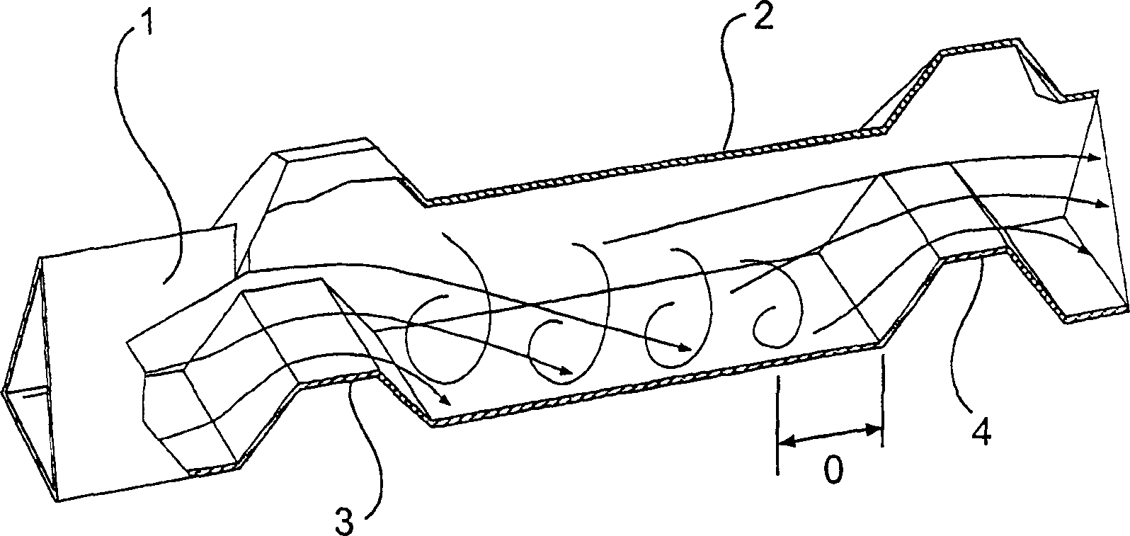
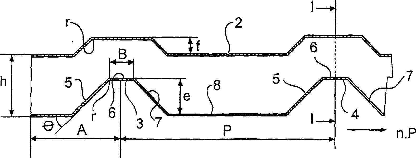
[0020] figure 1 and figure 2 The inlet 1 and a part of the piping 2 of the heat / moisture exchange device of the present invention are shown. In the figure, only the first turbulence generating device 3 and the second turbulence generating device 4 arranged closest to the inlet 1 are shown. The height of pipe 2 is h. The distance A between the open inlet and the center of the first turbulence generator 3 is determined by the ratio of the distance A to the product of the diameter of the turbulence and the Reynolds number which must be between 0.01-0.04. Here the turbulence diameter represents the ratio of the cross-sectional area of ​​the fluid pipe to the circumference of the pipe cross-section, and the Reynolds number is determined by the air flow.

[0021] It also follows from the above that A depends on the Reynolds number and thus on the gas flow velocity. Therefore, the optimal placement of the first turbulence generating device depends on the operating environment at...


PUM


Abstract

The invention relates to a device for heat / moisture exchange which has ducts (1) with turbulence generators (3, 4) extending transversely to the ducts and having a rear edge side (5), an upper side (6) and a front edge side (7). The device is characterised in that the ducts are such that the distance A between the inlet of the ducts and the centre of the nearest turbulence generator is determined by the ratio of the distance A to the product of the hydraulic diameter and Reynolds number being in the range of 0.01-0.04, that the angle theta which indicates the inclination of the rear edge sides (5) of the turbulence generators is in the range of 30 DEG -60 DEG , that the ratio of the height e of the upper side (6) above the bottom of the duct to the hydraulic diameter Dh is in the range of 0.3-1.1, that the ratio of the distance P between the turbulence generators (3, 4) to the height e is in the range of 8-30, that the ratio of the length B and the upper side (6) of each turbulence generator to the height e is in the range of 1.0-4.0, and that the ratio of the edge radius r of the turbulence generators to the hydraulic diameter Dh is in the range of 0.01-0.2.

Description

field of invention [0001] The present invention relates to a heat / moisture exchange device which optimizes the ratio of the respective conversion rates of heat and moisture relative to the pressure difference of the air flow passing therethrough. With this in mind, the exchange device is provided with a turbulence generating device extending perpendicularly to the pipe, the turbulence generating device having a trailing side, an upper side and a leading side. Background technique [0002] Air-to-air heat / moisture exchange devices as previously described are generally constructed of flat and corrugated strips assembled together to form triangular or trapezoidal ducts. In this type of heat / moisture exchange equipment, the cross-section of the pipe is small and the air flows quickly in the equipment environment, and the air flows in a relatively orderly layered manner along the direction of the pipe. Therefore, the airflow is laminar in nature. Only for a short distance from ...

Claims


Application Information

Patent Timeline
IPC IPC(8): F24F13/04F28F1/42F28F13/12
CPCF28F1/426F28F13/12F28F1/42F24F2221/46F24F13/04
Inventor 斯万·梅尔克·尼尔松
Owner 斯万·梅尔克·尼尔松
Features
  • R&D
  • Intellectual Property
  • Life Sciences
  • Materials
  • Tech Scout
  • Unparalleled Data Quality
  • Higher Quality Content
  • 60% Fewer Hallucinations
Learn More