Electric connector and socket connector

A socket connector and electrical connector technology, which is applied in the direction of connection, parts and circuits of connecting devices, etc., can solve the problems of damage to the connector and difficulty in pulling out the socket.

Inactive Publication Date: 2003-09-03
JST MFG CO LTD
View PDF0 Cites 7 Cited by
  • Summary
  • Abstract
  • Description
  • Claims
  • Application Information

AI Technical Summary

Problems solved by technology

[0007] However, it is still difficult to pull out the socket due to the different pull-out direction of the socket connector and the extension direction of the electric wire by adopting the compromise method, and both connectors may be damaged if the force is improper.

Method used


Image

  • Electric connector and socket connector
  • Electric connector and socket connector
  • Electric connector and socket connector

Examples


Embodiment Construction

[0022] Next, specific embodiments of the present invention will be described with reference to the drawings.

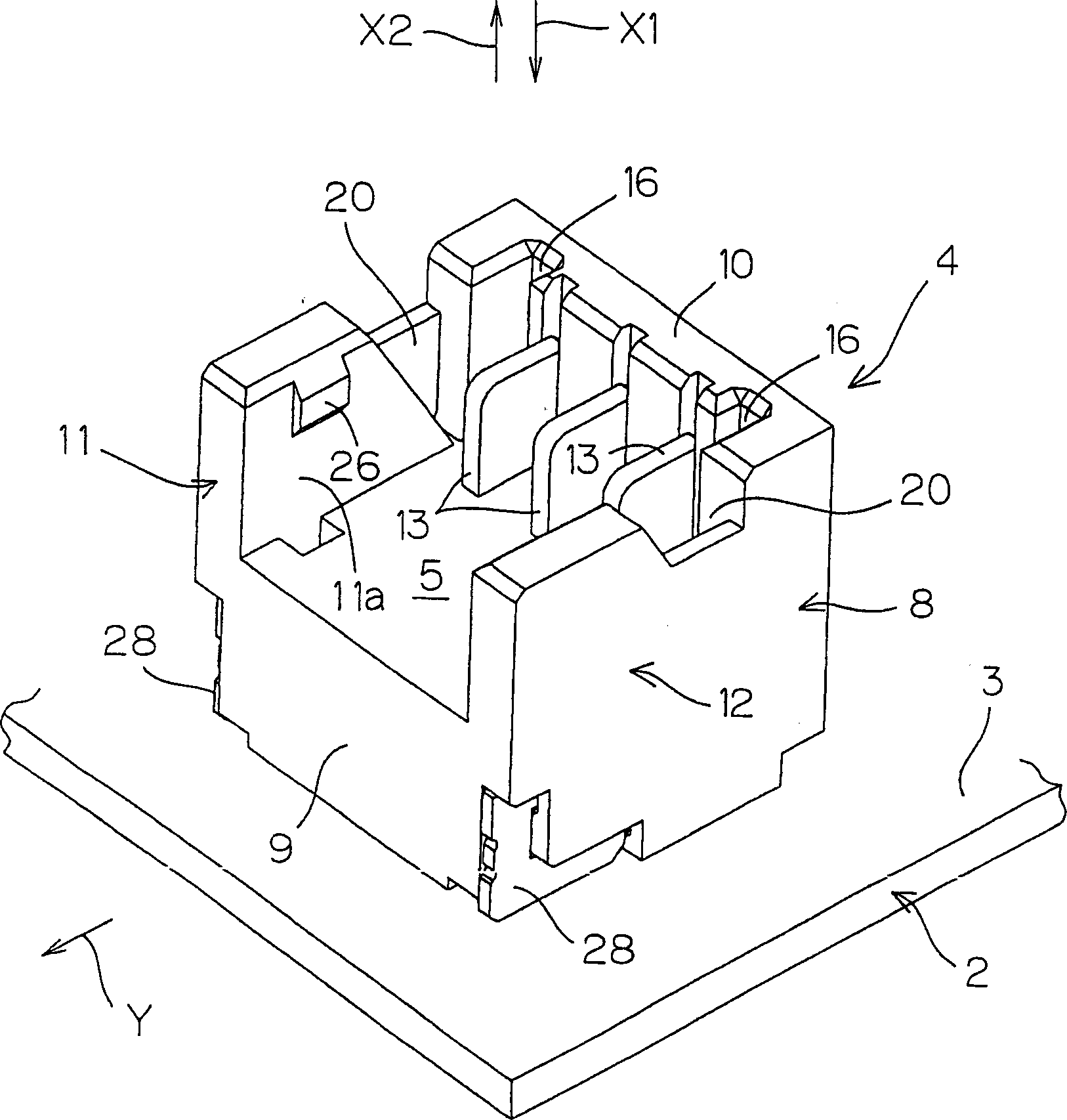
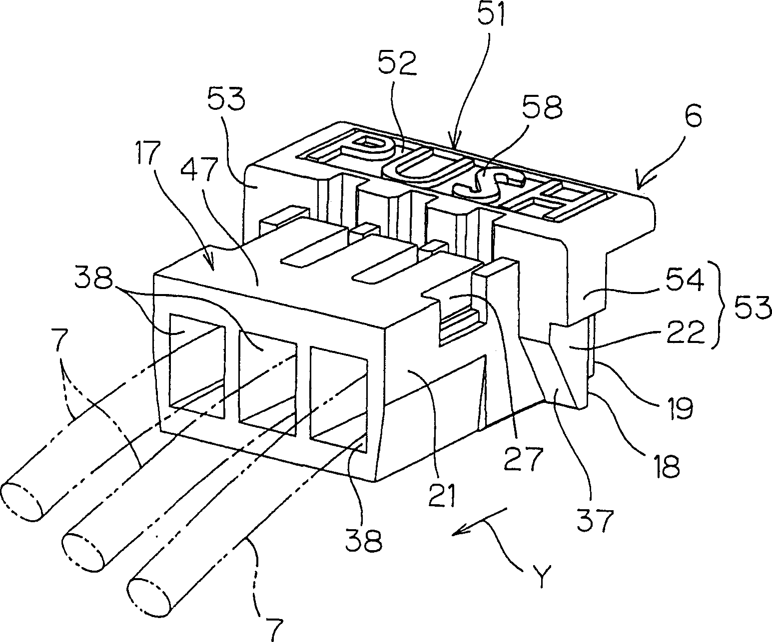
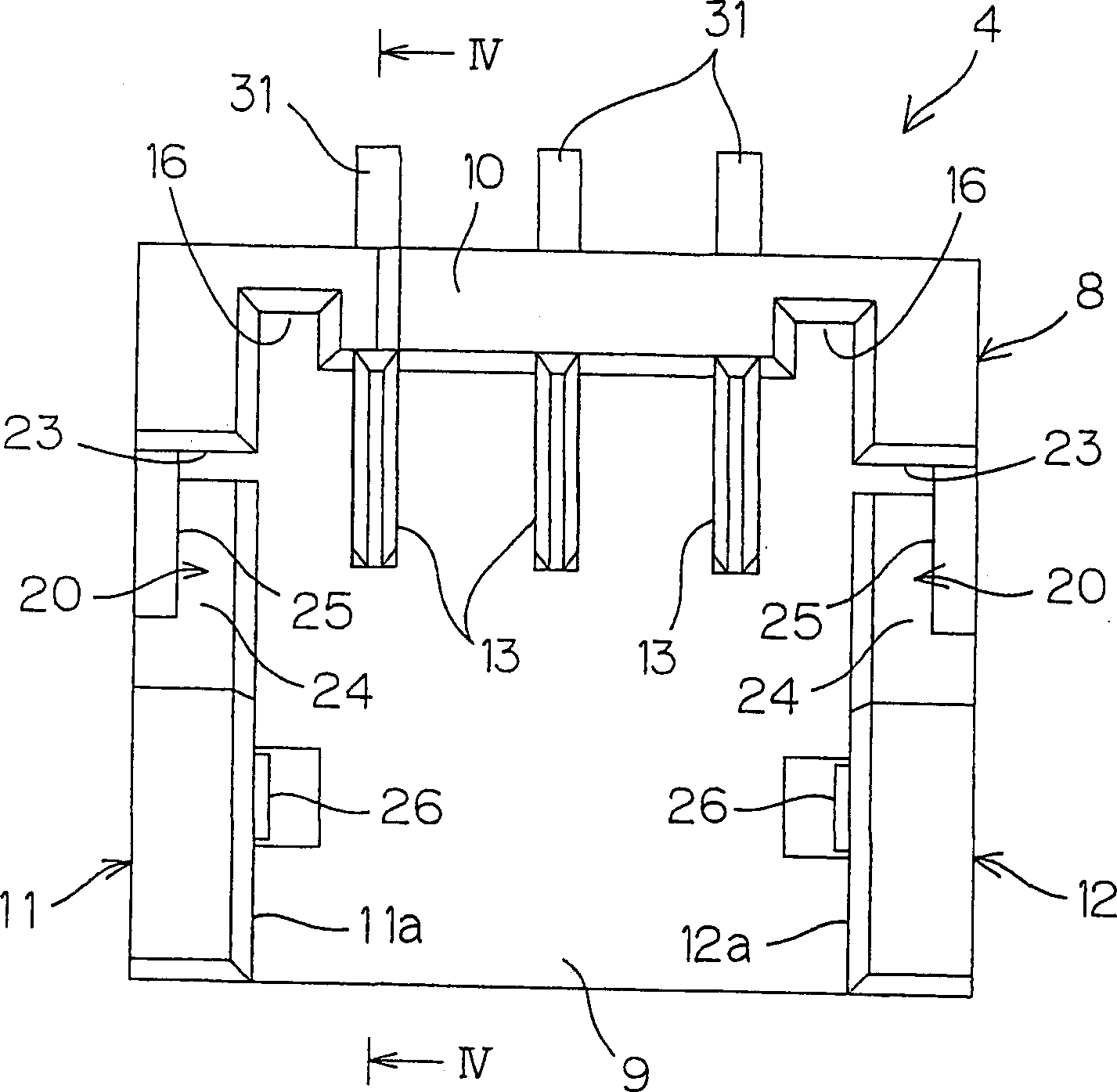
[0023] figure 1 and figure 2 It is a schematic perspective view showing a basic connector and a socket connector included in an electrical connector according to an embodiment of the present invention, Figure 10 It is a side view showing an electrical connector combining two connectors. With reference to these figures, it can be seen that the electrical connector 1 is equipped with a basic connector 4 fixed on the mounting surface 3 of the substrate 2 by soldering and can be inserted into the insertion space 5 of the basic connector 4 when matched with the basic connector 4 . The socket connector 5 for plugging and unplugging. For example, this electrical connector can be used in the connection between the substrate of the handy phone, PHS, etc. and the battery.

[0024] refer to figure 1 and figure 2 It can be seen that the insertion space 5 of the basic con...


PUM


Abstract

An electric connector, comprising a base connector (4) fixed onto a mounting surface (3) and a socket connector (6) extracted from the inserting space (5) of the base connector (4) along the extracting direction (X2) generally orthogonal to the mounting surface (3), wherein, when an electric conductor (7) extending in the direction parallel with the mounting surface (3)(Y) is pulled in the direction parallel with the mounting surface (3)(Y), a tension is converted into a force in the direction of extracting the socket connector (6) (X2) by the activation of the cam surface (24) of the base connector (4) and the cam surface (37) of the socket connector (6), whereby the socket connector (6) can be removed smoothly.

Description

technical field [0001] The present invention includes an electrical connector and a socket connector composed of a basic connector fixed on the surface of a substrate and a socket connector that can be pulled out from the basic connector along a direction perpendicular to the substrate. Background technique [0002] In recent years, the popularization of handy phones and PHS (Personal Handyphone System) etc. has made amazing progress. In the case of hand-held phones and the like, users who have purchased the machine have already assembled the built-in battery connector on the connector on the board or the like. Also, since the battery has reached the end of its life, there are many operations performed by users themselves to exchange it with a new product. [0003] The main reason for the unaccustomedness to this operation is the removal operation of the connector. At this time, because the two connectors are not well assembled, poor contact is often caused. In addition, ...

Claims


Application Information

Patent Timeline
Patent Type & Authority Applications(China)
IPC IPC(8): H01R13/11H01R13/115H01R13/46H01R13/629
CPCH01R12/79H01R12/716H01R13/113H01R13/62905H01R13/633
Inventor 清水一臣佐佐木昭一
Owner JST MFG CO LTD
Why Eureka
Try Eureka