Hand operated spray

A technology of injectors and nozzles, applied in the field of manual injectors, which can solve the problems of reducing the rotation of the swirl mechanism and product leakage

Inactive Publication Date: 2003-09-10
SAINT GOBAIN CALMAR SA
View PDF1 Cites 5 Cited by
  • Summary
  • Abstract
  • Description
  • Claims
  • Application Information

AI Technical Summary

Problems solved by technology

[0005] Furthermore, where the swirl mechanism is formed on the inner surface of the base of the spout cup, where the inner surface cooperates with the face on the injector body extending into the cup against the probe, the spout cup responds to the applied high pressure Any slight movement in the downstream direction will cause product leakage and will reduce the ability of the swirl mechanism to swirl the product and break it up into a fine spray

Method used


Image

  • Hand operated spray
  • Hand operated spray

Examples


Embodiment Construction

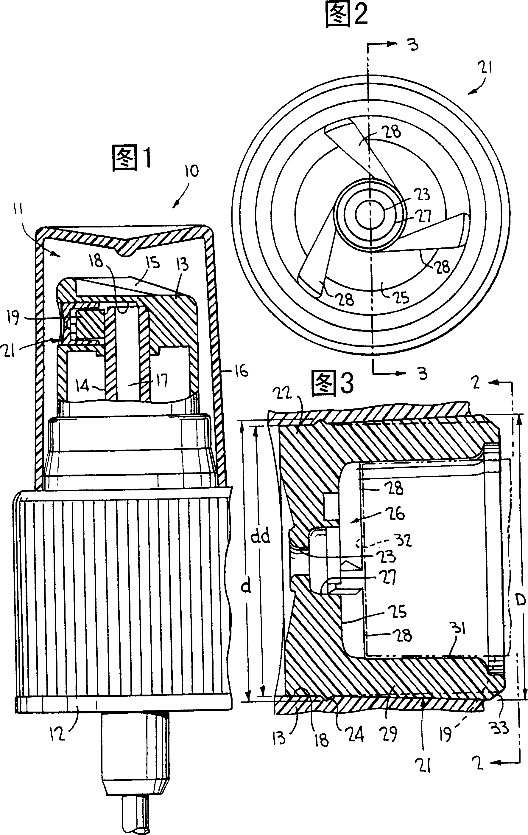
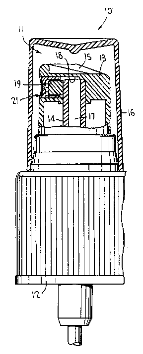
[0013] Reference is now made to the drawings, wherein like reference numerals indicate like and corresponding parts throughout the several drawings. The manual sprayer, indicated generally at 10 in Figure 1, is a pump sprayer of the type disclosed in US Pat. No. 4,051,983, which is incorporated herein by reference. Of course, other types of manual hand-held sprayers may also employ the present invention, such as trigger-actuated pump sprayers, aerosol sprayers, squeeze bottle sprayers, and the like.

[0014] The sprayer 10 has a body part 11 which includes a cap 12 for mounting the sprayer on a container (not shown) of the product to be sprayed. The body part also includes a plunger head 13 mounted on a hollow plunger rod 14 having features that can be moved in a manner known in the art when external finger pressure is applied to the top 15 of the plunger head. A pump piston (not shown) reciprocates within a cylinder (not shown). Of course, the top cap 16 is first removed by...


PUM


Abstract

A manually actuated sprayer has an orifice cup with a reverse taper mounted within a cylindrical bore of the discharge passage for positively retaining the orifice cup in place without dislodgement during spray actuation.

Description

technical field [0001] The present invention relates generally to manual sprayers (or sprayers) and, more particularly, to sprayers having a spout cup with a spout through which product is dispensed upon actuation of the sprayer. Background technique [0002] The known orifice cup fits within the discharge passage of a manual hand-held sprayer, the cup being press-fitted at its cylindrical side wall into the wall of the circular bore so as to remain generally immobile when in tight frictional engagement therewith . A swirl mechanism in the form of a swirl chamber and tangential passages leading thereto are formed on the inner surface of the circular bottom wall of the spout cup. When the injector is manually actuated (such as by squeezing the plunger tip to actuate a pump injector or by pressing a trigger to actuate a trigger), the liquid product is forced through the spray before it is dispensed as a spray through the discharge spout. Considerable pressure builds up throu...

Claims


Application Information

Patent Timeline
Patent Type & Authority Applications(China)
IPC IPC(8): B05B11/00B05B1/34
CPCB05B1/3436B05B11/00
Inventor 道格拉斯·B·多布斯约瑟夫·纳扎里
Owner SAINT GOBAIN CALMAR SA
Why Eureka
Try Eureka