Variable geometry Turbocharger

A turbocharger, geometric size technology, applied in gas turbine installations, machines/engines, combustion engines, etc., can solve problems such as increased manufacturing cost and structural complexity

Inactive Publication Date: 2003-10-22
GARRETT TRANSPORATION I INC
View PDF1 Cites 20 Cited by
  • Summary
  • Abstract
  • Description
  • Claims
  • Application Information

AI Technical Summary

Problems solved by technology

[0005] Although multi-impeller variable nozzle turbochargers have greatly improved overall efficiency and significantly increased turbocharger capacity, the complexity of the structure for the support and actuation of the impellers increases manufacturing costs and occasionally maintenance problem

Method used


Image

  • Variable geometry Turbocharger
  • Variable geometry Turbocharger
  • Variable geometry Turbocharger

Examples


Embodiment Construction

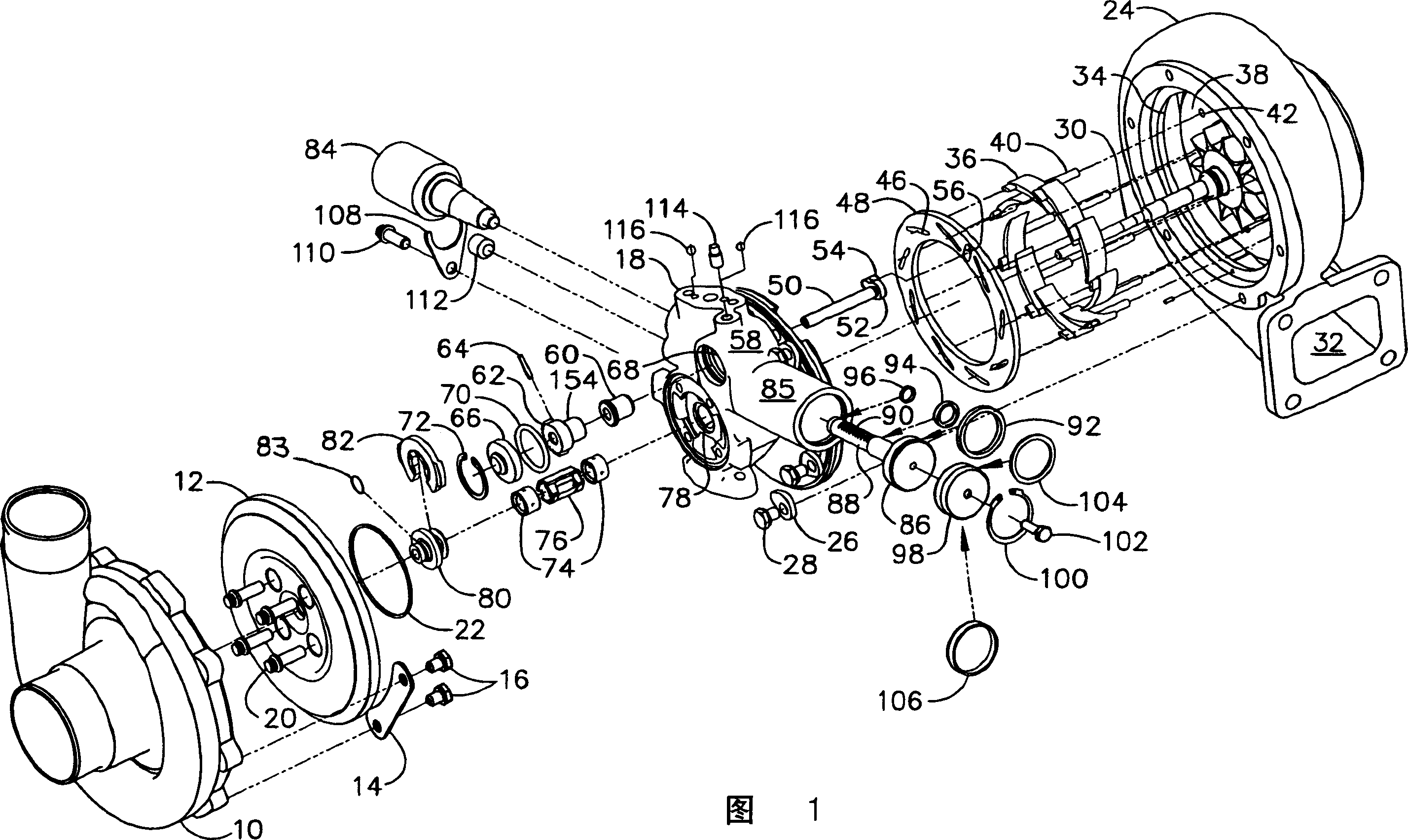
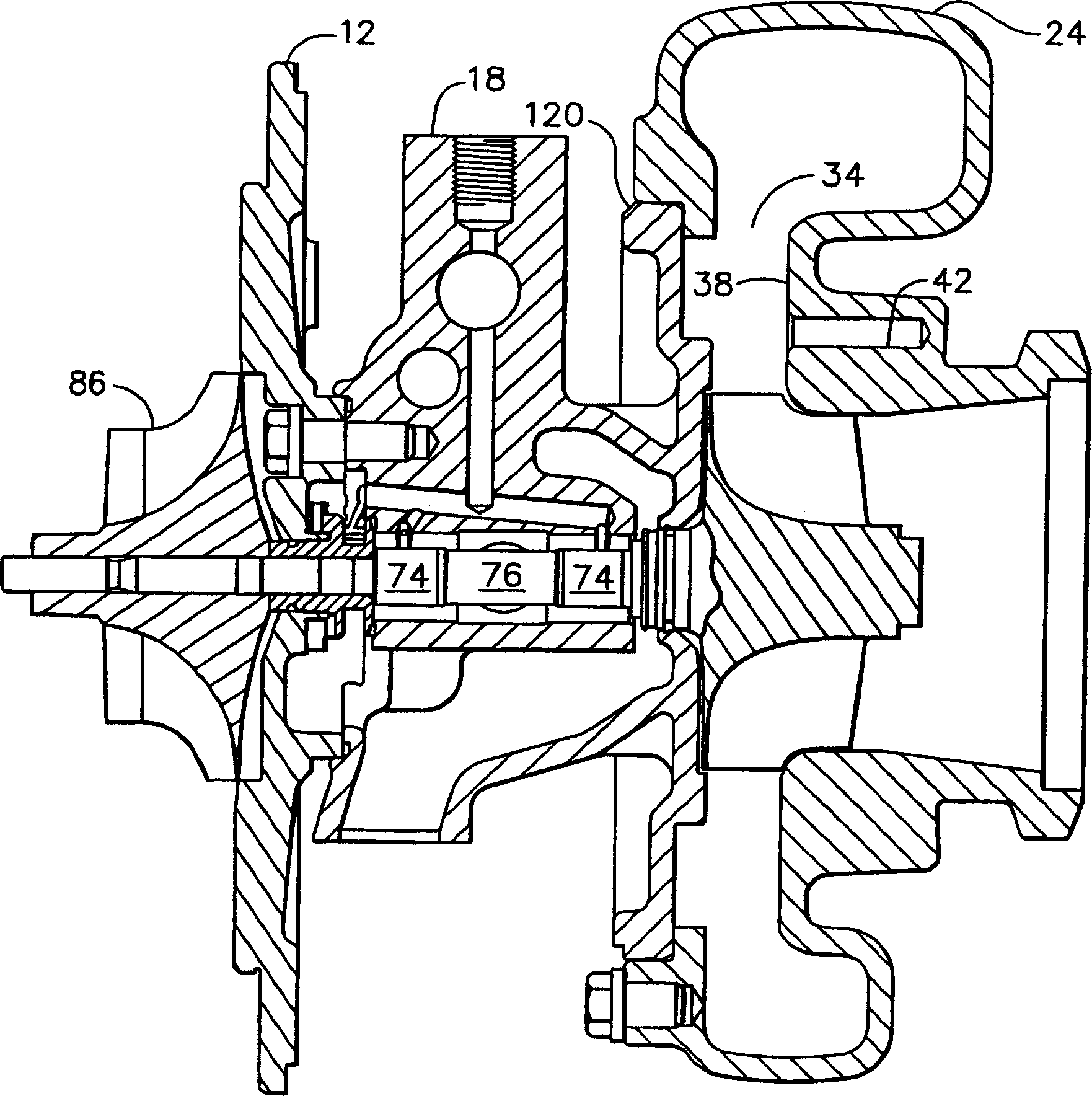
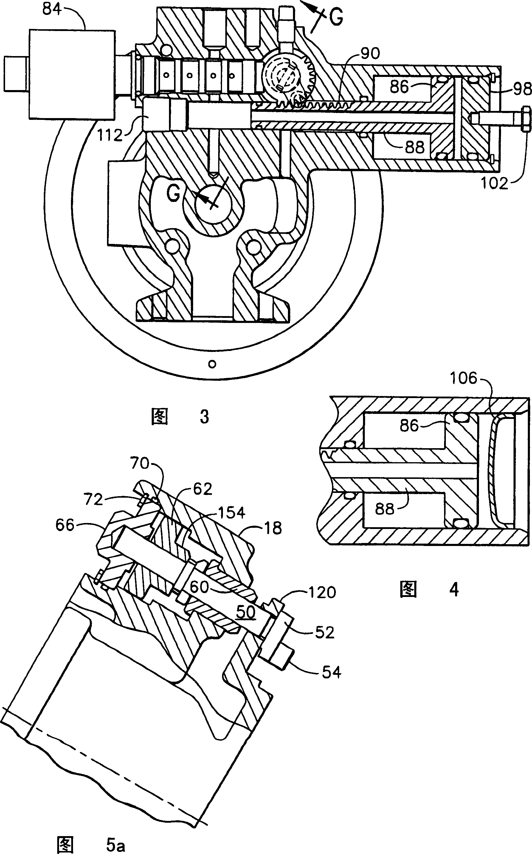
[0021] Referring to the drawings, the embodiment of the invention shown in FIG. 1 includes a compressor housing 10 attached to a back plate 12 using two or more clamps 14 secured by bolts 16. . The backplate is attached to a center housing 18 with bolts 20 and a seal ring 22 . The turbine housing 24 is connected to the center housing with a plurality of clamps 26 secured by bolts 28 . A turbine wheel and shaft assembly 30 is mounted within the turbine housing. Exhaust gases or other high energy gases supplied to the turbocharger enter the turbine housing through an inlet 32 ​​and are distributed through a volute within the turbine housing for substantially radial entry into the turbine through a circumferential nozzle inlet 34 impeller.

[0022] A plurality of vanes 36 are mounted to a nozzle wall 38 machined in the turbine housing with struts 40 extending from the vanes for rotational engagement with holes 42 in the nozzle wall. Actuation tabs 44 extend from the vanes to ...


PUM


Abstract

A variable geometry turbocharger employs multiple vanes (36) in the turbine inlet with a unison ring (48) and integral cast wall in the turbine housing forming the nozzle walls. The unison ring incorporates actuation slots (46) receiving tabs (44) on the vanes (36) for opening the closing the nozzle area upon rotation of the unison ring (48). An integral electrohydraulic actuator rotates the unison ring (48) through a rack and pinion driven crank shaft with direct position feedback to the spring biased variable current solenoid via a cam on the crank shaft.

Description

Background of the invention [0001] technical field [0002] The present invention relates generally to the field of turbochargers with variable turbine inlet geometries. More specifically, the present invention provides a simplified structural means for positioning a plurality of aerodynamic impellers within the inlet nozzle of a turbine housing and an integral actuator for controlling the position of the impellers. [0003] Background technique [0004] In turbochargers it is often desirable to control the flow of exhaust gas into the turbine to improve efficiency or operating range. Various nozzle configurations have been employed to control exhaust flow. An approach that has been successfully employed in prior art turbochargers is a plurality of pivoting impellers positioned annularly about the turbine inlet and controlled together to vary the throat area of ​​the passage between the impellers. In U.S. Patent No. 4,679,984 to Swihart et al., entitled "Actuation Syste...

Claims


Application Information

Patent Timeline
Patent Type & Authority Applications(China)
IPC IPC(8): F02B37/24F01D17/16F02C6/12
CPCF01D17/165F05D2220/40F05B2220/40F02B37/22
Inventor S·D·阿诺V·卡尼戈夫斯基K·斯卢普斯基S·P·马丁
Owner GARRETT TRANSPORATION I INC
Why Eureka
Try Eureka