Direct lever overhead valve system

A lever and lever arm technology, applied in the field of directional lever valve jacking system

Inactive Publication Date: 2003-11-19
BRIGGS & STRATTON
View PDF1 Cites 3 Cited by
  • Summary
  • Abstract
  • Description
  • Claims
  • Application Information

AI Technical Summary

Problems solved by technology

But Everts' US patent is a complex combination of elements operating between the cam and the valve

Method used


Image

  • Direct lever overhead valve system
  • Direct lever overhead valve system
  • Direct lever overhead valve system

Examples


Embodiment Construction

[0020] Before explaining the embodiments of the present invention in detail, it should be understood that the present invention is not limited to the arrangement of components and structural settings in the following drawings and embodiments. The invention can be implemented in a variety of ways. And it can also be understood that the words and technical terms used herein are for the purpose of description, and should not be interpreted as a limitation. The use of "including" and "comprising" and the different embodiments here all mean to include All parts plus additional parts.

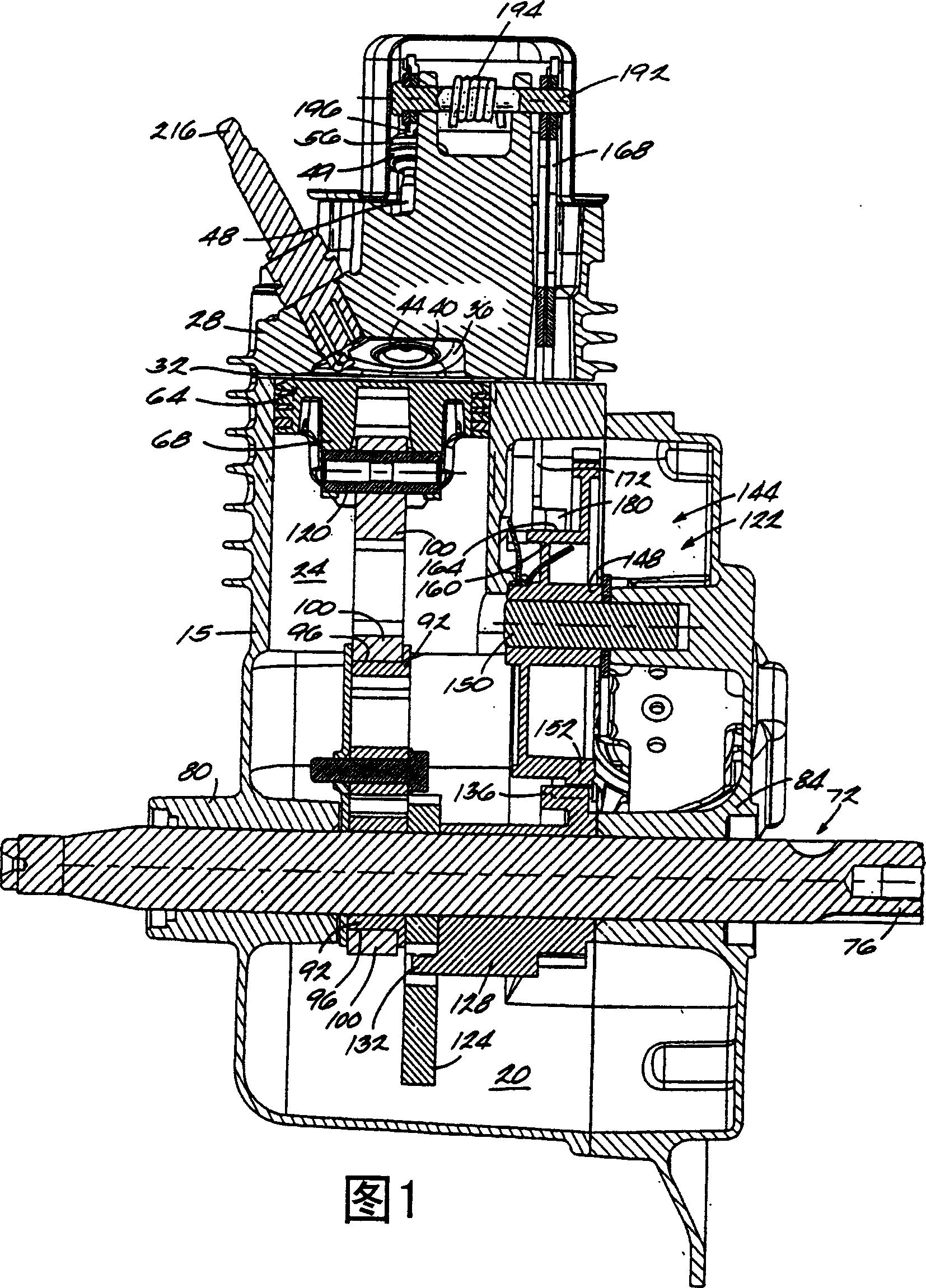
[0021] FIG. 1 is a cross-sectional view of an overhead valve engine 10 . The overhead valve engine includes an engine housing 15 which in turn includes a crankcase 20 and cylinder bores 24 . It should be noted that, here, "outside" refers to the direction away from the crankcase 20, "inside" refers to the direction towards the crankcase 20, and the cylinder bore 24 has an outer end 32, where the cy...


PUM


Abstract

An overhead valve engine including a cylinder bore having an outer end; and a crankshaft assembly including a substantially straight crankshaft, a substantially cylindrical journal eccentrically mounted on the crankshaft, a one-piece connecting rod rotatably mounted on the journal, and a counterweight mounted on the crankshaft. The engine also includes a cam shaft having at least one cam surface and an axis inward of the outer end of the cylinder bore; two valves having opened and closed positions; two valve stems, each valve stem being attached to a valve; and two generally L-shaped and pivotably mounted valve operating levers, each lever including a first lever arm having a cam follower in contact with the cam surface, a pivot axis about which the lever pivots, and a valve arm in contact with a valve stem, where movement of the lever caused by the cam surface causes the lever to pivot and the valve arm to depress the valve stem and thus open the valve.

Description

technical field [0001] The present invention generally relates to an internal combustion engine, in particular to a directional lever top valve system capable of controlling valve closing. Background technique [0002] As we all know, in the valve operating system of the overhead valve engine, the movement of the valve can be controlled by combining the push rod and the rocker through the V-shaped cam follower. US Patent No. 5,357,917 to Everts is an example of this. But Everts' US patent is a complex combination of elements operating between the cam and the valve. Brief description of the invention [0003] The present invention provides a directional lever top valve system designed to directly control valve operation based on cam rotation. Directional lever top valve systems are especially useful for simplifying valve operation by transferring the cam rotation directly to the valve stem. [0004] A directional lever system may utilize a pair of generally L-shaped leve...

Claims


Application Information

Patent Timeline
Patent Type & Authority Applications(China)
IPC IPC(8): F02B67/04F01L1/02F01L1/12F01L1/18F01L13/08F02B63/02F02B75/16F02F1/24
CPCF02B75/16F01L13/085F01L13/08F02B63/02F01L1/024B21C23/142
Inventor 加里·J·格拉齐阿尼理查德·J·福查戴维·普洛克诺阿特·帕尔曼斯科特·A·芬克
Owner BRIGGS & STRATTON
Why Eureka
Try Eureka