Terminal structure of extreme-low temperature equipment

A technology of low-temperature equipment and terminal structure, which is applied in the direction of low-temperature cable cable accessories, cable terminals, equipment for connecting/terminating cables, etc., and can solve problems such as difficult regenerative cooling, deterioration of insulation performance, and increased system loss

Inactive Publication Date: 2003-11-19
SUMITOMO ELECTRIC IND LTD +1
View PDF0 Cites 23 Cited by
  • Summary
  • Abstract
  • Description
  • Claims
  • Application Information

AI Technical Summary

Problems solved by technology

As a result, the energy required for cooling becomes a loss, increasing the overall system loss
[0010] (2) It is difficult to use the closed system of the refrigerant tank for regenerative cooling
[0016] (3) When the space inside the sleeve 30 communicates with the gas container 42 in the insulator 40, the insulation performance may deteriorate
However, in order to ensure that the pressure is large enough so that the insulation performance will not be affected after cooling, the pressure before cooling should be very large, which is unrealistic
[0020] (4) When the space inside the sleeve 30 is not in communication with the gas container 42 in the insulator 40, excessive pressure changes inside the sleeve can cause mechanical damage
Thus, very high pressure can cause mechanical damage to the sleeve 30

Method used


Image

  • Terminal structure of extreme-low temperature equipment
  • Terminal structure of extreme-low temperature equipment
  • Terminal structure of extreme-low temperature equipment

Examples


no. 1 example

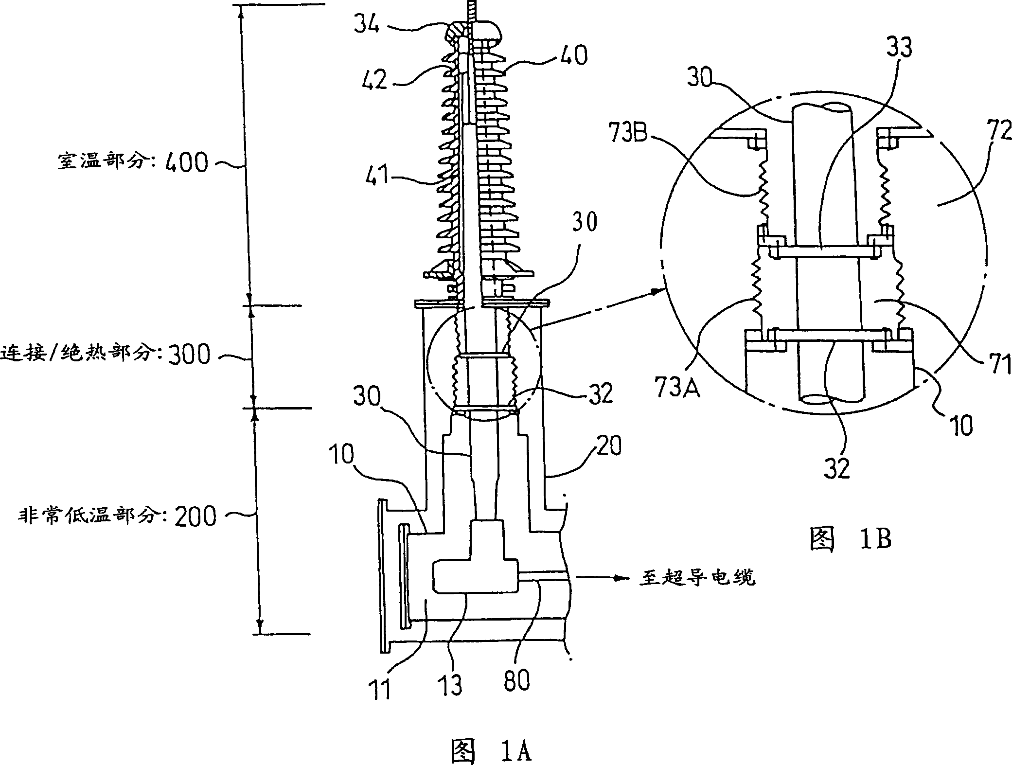
[0085] Now, the terminal structure of the superconducting cable will be described by way of example. FIG. 1 is a schematic diagram of a terminal structure according to the present invention. This terminal structure has: a very low temperature part immersed in the liquid nitrogen 11 in the cryogen tank 10; a room temperature part 400 placed in the insulator 40; and a connection / connection formed between the very low temperature part 200 and the room temperature part 400 Insulation portion 300.

[0086] The vacuum vessel 20 is connected to a heat insulating tube (not shown) of the superconducting cable. A vacuum is maintained in the vacuum vessel 20 at the portion connected to the heat insulating tube and in the heat insulating tube. In this embodiment, the opening diameter of the vacuum vessel 20 is set to φ600 mm.

[0087] The connecting conductor 80 , which is connected to the insulator 40 of the superconducting cable, leads into the cryogen tank 10 . The cryogen tank 10 ...

no. 2 example

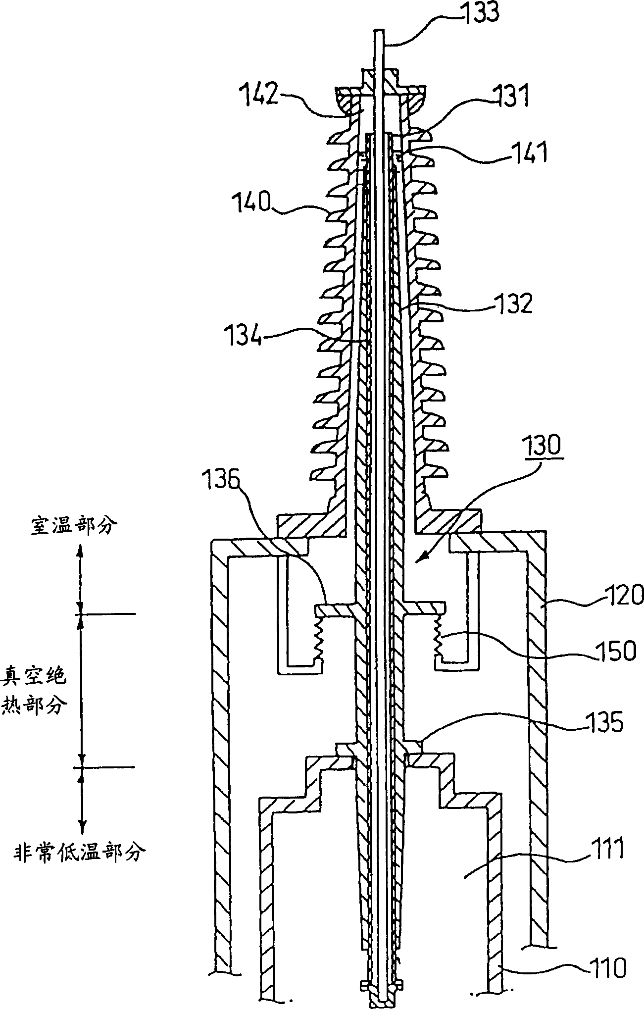
[0104] Now, the terminal structure of the superconducting cable will be explained with the help of an example. image 3 is a schematic diagram of a terminal structure according to the present invention. The terminal structure has: a very low temperature part 200 immersed in liquid nitrogen 111 in a cryogen tank 110; a room temperature part 400 placed in an insulator 140; and a connection / connection formed between the very low temperature part and the room temperature part Insulation portion 300.

[0105] A connection conductor connected to a conductor of a superconducting cable, not shown, leads through the vacuum vessel 120 into the cryogen tank 110 forming part of the cryogenic part 200 . The cryogen tank 110 is a cylindrical tube into which liquid nitrogen 111 is hermetically filled. In the refrigerant tank, the above-mentioned connection conductor is connected to the sleeve 130 (conductor portion).

[0106] The cryogen tank 110 of this structure is placed in the vacuum ...

no. 3 example

[0117] Figure 4 An example in which the structure of the room temperature part is different is shown. The structure of the third embodiment is the same as that of the first embodiment except that the structure of the end portion of the room temperature portion is different. Therefore, differences will be mainly described.

[0118] The structure of the room temperature part is that the sleeve 130 is placed in the insulator, but the space 134 formed in the sleeve 130 does not communicate with the air gap part 142 formed above the insulating oil container. In this case, a vacuum is created in the space inside the sleeve, or the space inside the sleeve is filled with helium gas that does not liquefy at extremely low temperatures. The space inside the sleeve is sealed by welding the end of the stainless steel pipe 131 or the like. With this structure, liquefaction of the substance inside the sleeve can be prevented, so that an excessive pressure change in the sleeve can be supp...


PUM


Abstract

A terminal structure of cryogenic equipment for leading a terminal of cryogenic equipment 100 from a very low temperature portion to a room temperature portion through a bushing, having a feature in that a connecting / heat-insulating portion 300 adiabatically connected with the aforementioned very low temperature portion 200 and the aforementioned room temperature portion 400 is provided along the outer circumference of the aforementioned bushing 30 between the aforementioned very low temperature portion 200 and the aforementioned room temperature portion 400.

Description

technical field [0001] The present invention relates to termination structures for conducting conductors of cryogenic devices from very low temperatures to room temperature. More specifically, it relates to terminal structures that are thermally insulative or have very good thermal insulation properties. Background technique [0002] Figure 7 is a schematic diagram representing a conventional terminal structure for a cryogenic device. [0003] This terminal structure has a terminal of a cryogenic device 100 (not shown); a cryogen tank 10 accommodating the terminal; a conductive sleeve 30 protecting the conductors of the vacuum vessel 20 leading to the room temperature portion; a vacuum container 20 outside the box 10; and an insulator 40 connected to the upper portion of the vacuum container 20 to protrude from the vacuum container. [0004] The sleeve 30 is connected to the superconductor introduced from the cryogenic device 100 substantially at right angles. The core o...

Claims


Application Information

Patent Timeline
Patent Type & Authority Applications(China)
IPC IPC(8): H02G15/22H02G15/34
CPCH02G15/34H01B17/36
Inventor 芦辺佑一广濑正幸古川晃平高桥芳久松尾公义本庄升一三村智男相场辉光
Owner SUMITOMO ELECTRIC IND LTD
Why Eureka
Try Eureka