Hand dryer

A technology of hand drying and blowing devices, which is applied in household appliances, sanitary equipment, pneumatic massage, etc., can solve the problems of position staggering, and achieve the effect of eliminating shedding and high safety

Inactive Publication Date: 2004-01-07
MATSUSHITA SEIKO CO LTD
View PDF1 Cites 7 Cited by
  • Summary
  • Abstract
  • Description
  • Claims
  • Application Information

AI Technical Summary

Problems solved by technology

However, when the front case 102 is opened and closed, when the legs of the LED are knocked down due to th...

Method used


Image

  • Hand dryer
  • Hand dryer
  • Hand dryer

Examples


Embodiment Construction

[0067] Hereinafter, embodiments of the present invention will be described with reference to the drawings.

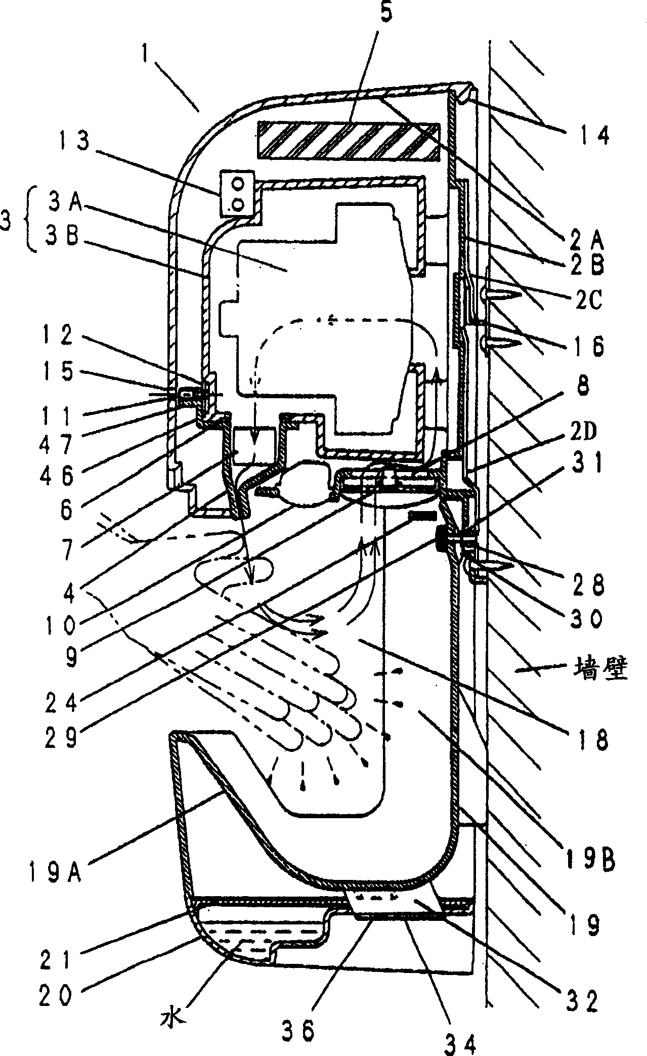
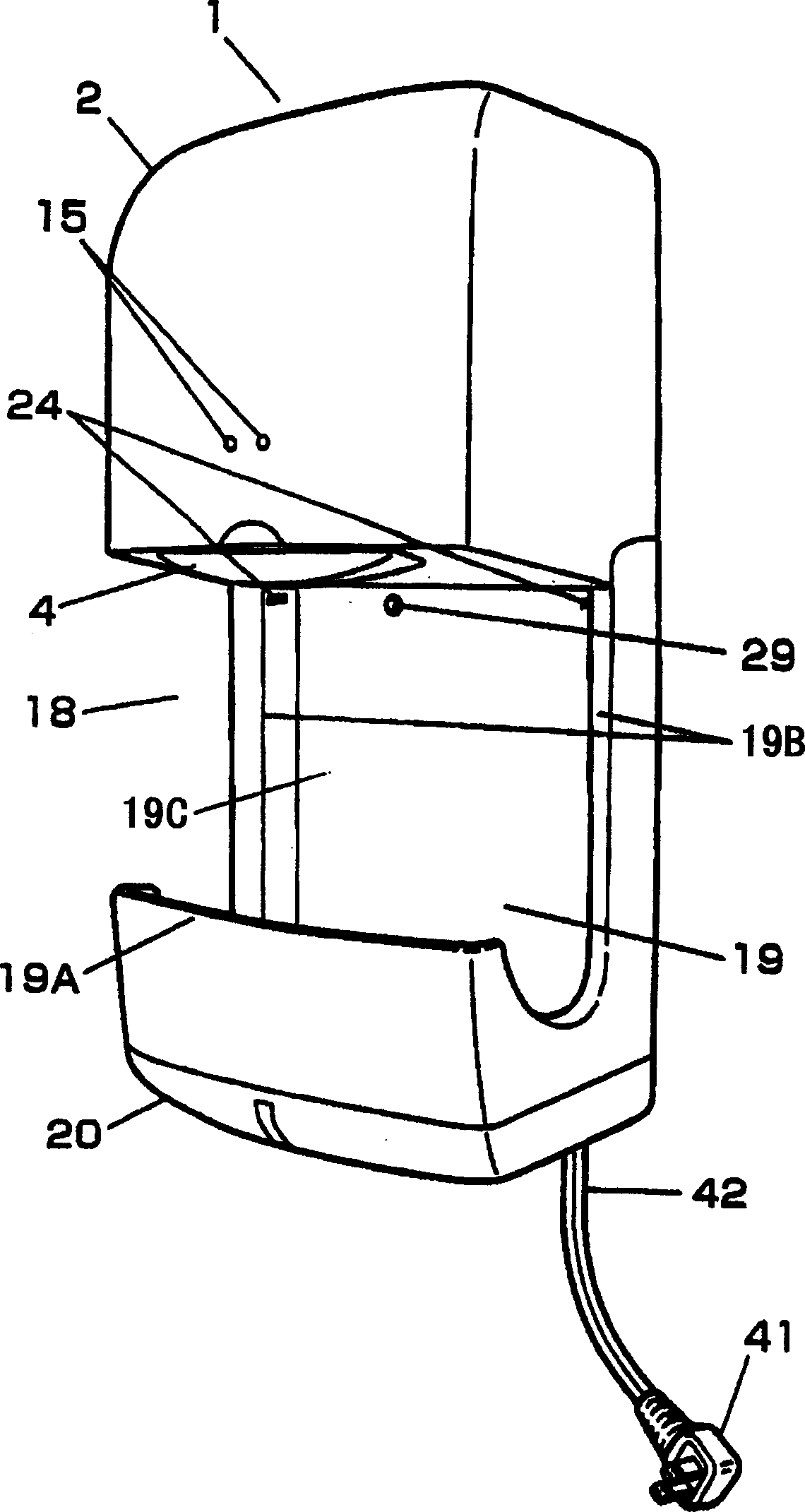
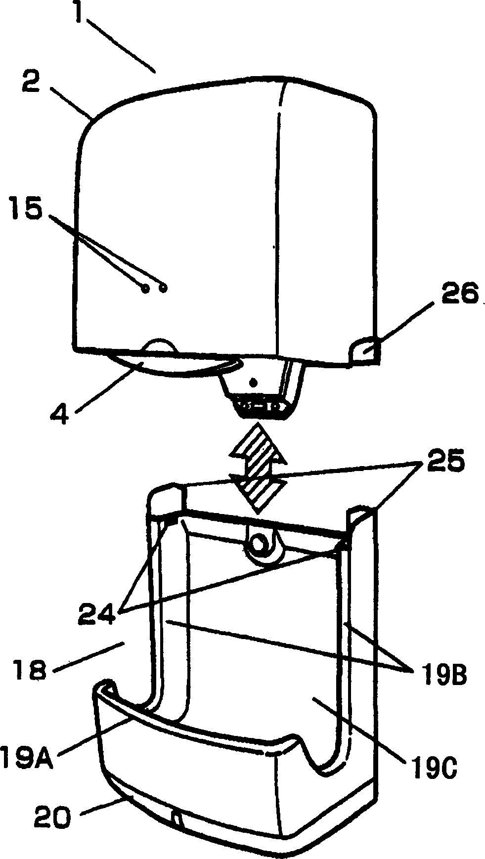
[0068] figure 1 It is a side sectional view of a hand dryer according to an embodiment of the present invention, figure 2 is a perspective view of the same hand dryer, image 3 It is a perspective view of the same hand dryer showing a state where the water receiving part is separated from the main body case, Figure 4 It is a perspective view of the same hand drying device showing the operation state of separating the water receiving part from the main body casing. A front sectional view of the main part of the same hand dryer showing the locking release device, Figure 7 Fig. 8 is a side sectional view of main parts of the same hand dryer showing the fixing bolts of the water receiving member.

[0069] Such as Figure 1 ~ Figure 3 5 and 6, the main body casing 1 is composed of a front casing 2A covering the front, top and both sides and a rear casing 2B covering...


PUM


Abstract

A hand dryer has a body case with a blower with an air-blowing nozzle on its lower surface, and a water receiver disposed below the body case and forming a hand-inserting space with the body case. The water receiver is detachable from the body case. The water receiver has a receiving portion which covers a lower front surface, a back surface which is connected to the receiving portion and which covers a wall surface, and a pair of side surfaces, connected to the receiving portion, rising from opposite sides of the back surface. Water receiver-side retaining portions are on upper portions of the side surfaces, body case-side retaining portions are on opposite sides of the body case, and the water receiver is mounted to the body case by the water receiver-side retaining portions and the body case-side retaining portions. The water receiver-side retaining portions are hooked on the body case-side retaining portions, so that the water receiver can be fixed.

Description

technical field [0001] The present invention relates to a hand drying device for drying wet hands when washing hands in a washroom or toilet. Background technique [0002] Conventionally, such a hand dryer is known as a hand dryer described in JP-A-10-99235. [0003] Below, refer to Figure 17 The hand dryer will be described. [0004] As shown in the figure, the body casing 101 fixed on the wall is composed of a front casing 102 and a water receiving tray 103 protruding from the lower part. A drying space 102 a is formed between the front case 102 and the water receiving tray 103 . Inside the front case 102 are provided a blowing device 104 , a heating device 105 and a control device 108 . Furthermore, the air blowing nozzle 106 is provided in the lower end part of the front cabinet 102 toward the drying space 102a. In addition, an air suction port 117 for sucking air into the air blowing device 104 is arranged at a lower portion on the back side of the water receiving ...

Claims


Application Information

Patent Timeline
IPC IPC(8): A47K10/48
CPCA47K10/48A47K2210/00A61H9/005
Inventor 田井泰
Owner MATSUSHITA SEIKO CO LTD
Why Eureka
Try Eureka