
Rapidly connecting electromagnetic relay with protruding arm movable spring extended sheet for limitation

A technology of electromagnetic relay and lead-out piece, which is applied in the direction of electromagnetic relay, electromagnetic relay details, relay, etc., which can solve the problems of high output isolation, failure to meet the use requirements, and small installation space

Active Publication Date: 2004-03-31
XIAMEN HONGFA ELECTROACOUSTIC CO LTD
View PDF1 Cites 0 Cited by
  • Summary
  • Abstract
  • Description
  • Claims
  • Application Information

AI Technical Summary

Problems solved by technology

As a result, such products cannot meet the requirements in the occasions requiring small installation space, high input and output isolation, and quick connection.

Method used


Image

  • Rapidly connecting electromagnetic relay with protruding arm movable spring extended sheet for limitation
  • Rapidly connecting electromagnetic relay with protruding arm movable spring extended sheet for limitation
  • Rapidly connecting electromagnetic relay with protruding arm movable spring extended sheet for limitation

Examples


Embodiment Construction

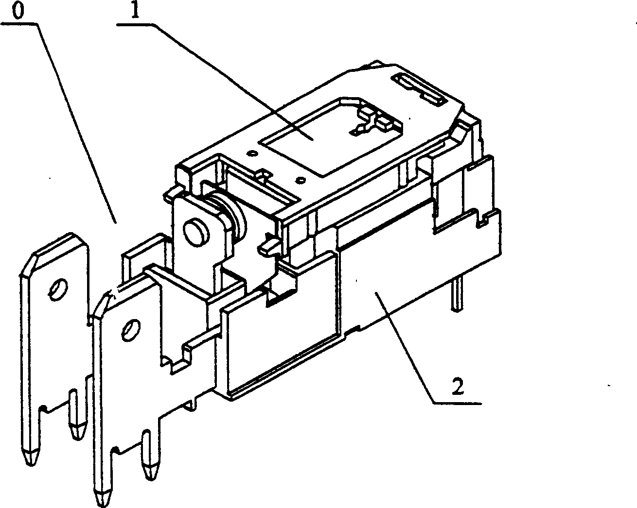
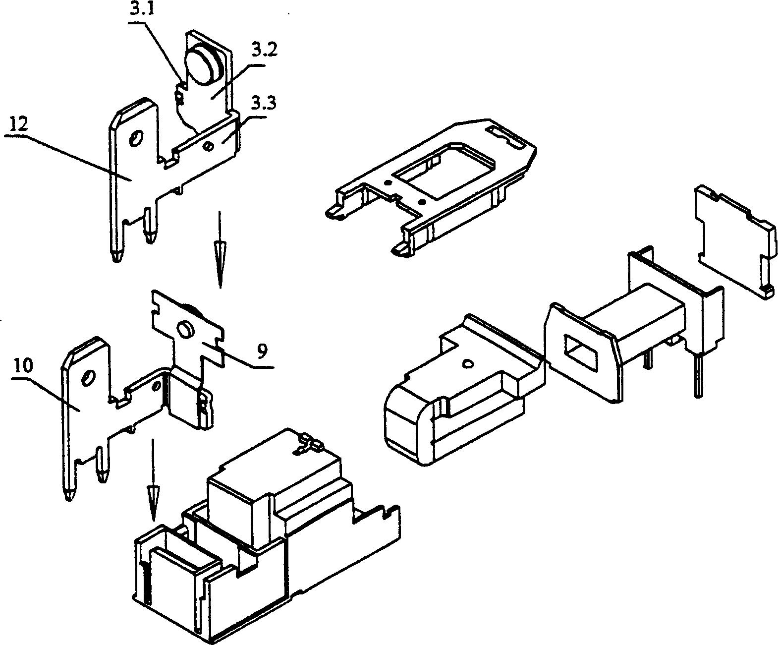
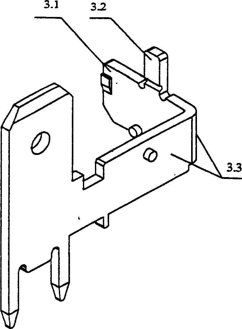
[0016] like figure 1 , 2, the present invention includes a magnetic circuit system 0, a contact system 1 and a base 2. see image 3 , 4. On one side 3.1 of the L-shaped moving spring lead-out piece 3 of the normally open contact structure of the contact system, there is a limit protrusion arm 3.2, which is used to limit the rebound position of the moving reed to ensure that the push block and There is a certain gap between the moving reeds 4 to reduce the initial driving voltage of the electromagnetic relay and achieve the purpose of quick connection.

[0017] On the base, an L groove 5.1 (see Figure 5 ).

[0018] The static spring 6 of the contact system is also designed in an L shape, and one side 6.1 is matched and clamped with the L groove 5.2 of the base (see Image 6 ).


PUM


Abstract

The invention refers to a quick-connecting electro-magnetic relay of dynamic spring eduction piece with positioning raised arm, including magnetic circuit system, contacting system and base. At leastone raised arm is set on the dynamic spring piece with normally opened contactor. The raised arm accurately limits the springback position of the dynamic piece to reduce initial pull-in voltage. The whole bulk of the relay is small. The one-way slot of the base contains the magnetic circuit to effectively enhance insulating property.

Description

(1) Technical field [0001] The invention relates to an electromagnetic relay, in particular to a low-height, small-sized, high-power electromagnetic relay with a limiting protruding arm, a movable spring lead-out piece, and quick connection. (2) Background technology [0002] As an electromechanical component, electromagnetic relay is widely used in various electromechanical equipment. Existing conventional small high-power AC electromagnetic relays generally include coils, coil leads, iron cores, yokes, armatures, springs, push blocks, moving reeds, static reeds, contacts, bases, and shells. Among them, the coil generally adopts the formal installation method, the iron core and the yoke are connected by riveting, and the lead-out pins generally adopt the PCB method or QC connection method, but the height direction of the product is large, and the isolation between the coil and the contact is also low. , The dielectric withstand voltage is not high. Generally, the conversio...

Claims


Application Information

Patent Timeline
IPC IPC(8): H01H50/54H01H50/56
Inventor 谭忠华
Owner XIAMEN HONGFA ELECTROACOUSTIC CO LTD
Learn More