Battery connector and method for mounting it on battery

A battery connector, electrical connection technology, applied in the direction of conductive connection, electrical component connection, electrical connection seat, etc., can solve problems such as adverse effects of other electronic equipment

Inactive Publication Date: 2004-06-16
SUMITOMO WIRING SYST LTD
View PDF1 Cites 8 Cited by
  • Summary
  • Abstract
  • Description
  • Claims
  • Application Information

AI Technical Summary

Problems solved by technology

If the individual circuits are short-circuited at this time, it may have adverse effects on other electronic equipment

Method used


Image

  • Battery connector and method for mounting it on battery
  • Battery connector and method for mounting it on battery
  • Battery connector and method for mounting it on battery

Examples


Embodiment Construction

[0039] Hereinafter, a preferred embodiment of the present invention will be described by way of example with reference to the accompanying drawings.

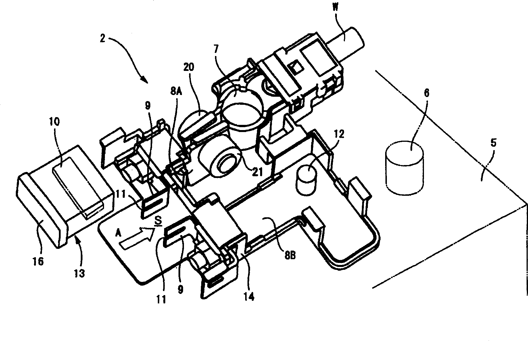
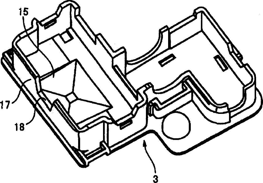
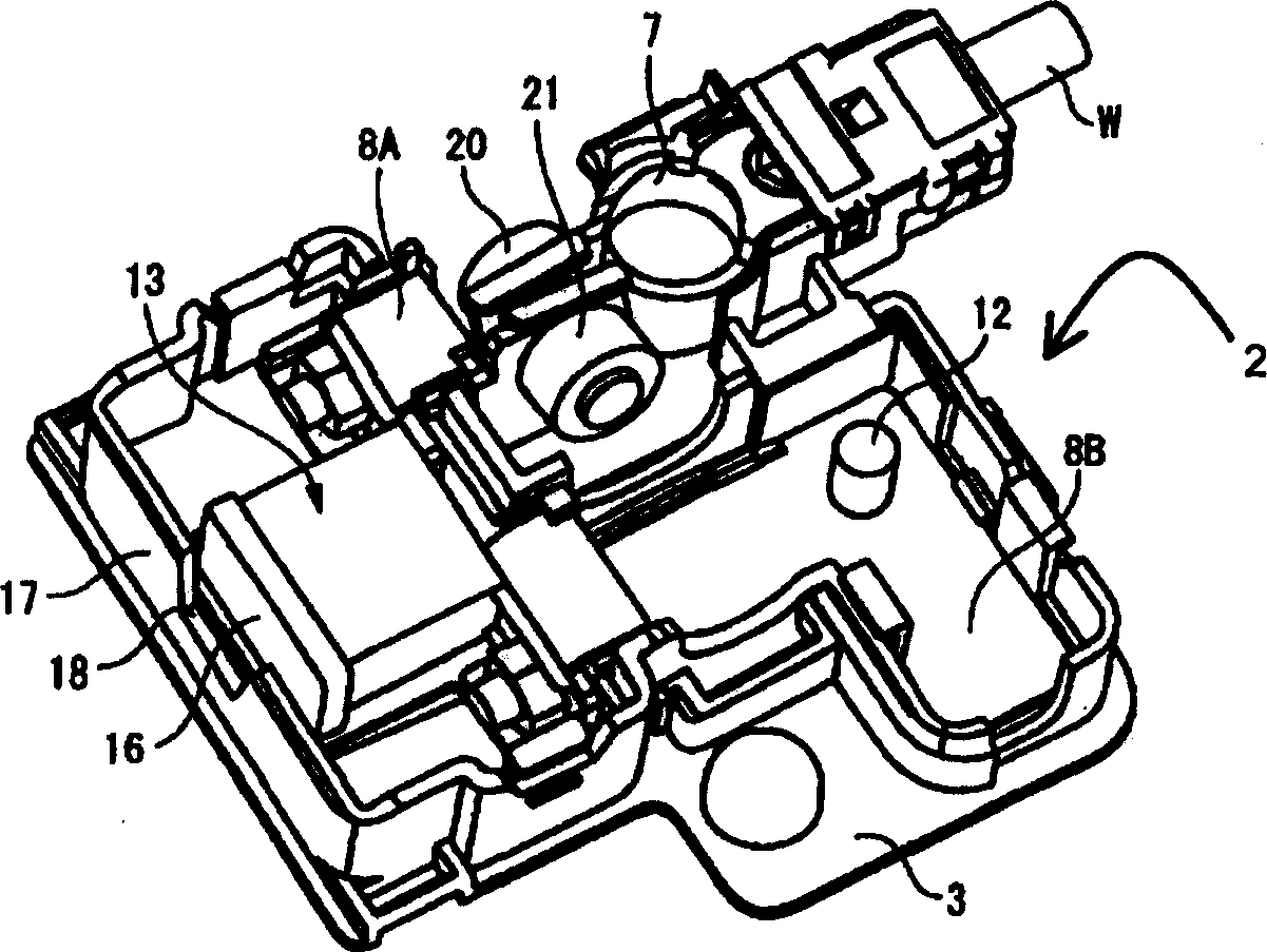
[0040] The battery connector 1 of this embodiment is connected to a battery terminal 6 of a battery 5 which is installed, for example, in a car and supplies power to at least two different circuits. The battery connector 1 is provided with a base unit 2 , a housing unit 3 and a cover unit 4 . base unit 2 as figure 1 Shown are: a base portion 14 which is mounted while positioning the various components; a battery terminal 7 which couples to a battery post 6 mounted on the battery 5; and one or more bus bars 8A, 8B.

[0041] A wire W is connected to one end of a battery terminal 7 to supply power to a circuit. Screws 20 and nuts 21 are fitted to the battery terminal 7 . The battery terminal 7 is fixed to the battery post 6 by fastening screws 20 and nuts 21 .

[0042] A pair of fuse connection portions 9 are provided at oppos...


PUM


Abstract

A battery-connecting member (1) has a base (2) for accommodating a fuse (10) and a casing (3) for accommodating the base (2). The base (2) includes a battery terminal (7), busbars (8A, 8B) and the fuse (10). A box-accommodating portion (15) is provided in the casing (3) for accommodating the fuse (10) and is provided with an operation space closing portion (17) at a side toward which the fuse (10) is detached. Thus, the fuse (10) cannot be detached unless the battery-connecting member (1) is detached from a battery (5) and the casing (3) and the base (2) are separated.

Description

technical field [0001] The invention relates to a battery connector and a method for installing it on a battery. Background technique [0002] Figure 5 and Figure 6 A battery connector 100 disclosed in Japanese Unexamined Utility Model No. S63-182048 is shown. The battery connector 100 is provided with: a battery terminal 101, which is fixed on a battery terminal 105; a bus bar 102, which is coupled to the battery terminal 101; a plurality of fuses 103, which are connected to the bus bar 102; and a case 104, which Include the above components. A cover 107 for covering the fuse 103 is integrated with the case 104 by a hinge. [0003] The battery connector 100 is connected to, for example, a battery 106 of a motor vehicle, thereby connecting multiple circuits (eg, a power circuit connected to a cell motor, circuits of devices connected to other electric devices, etc.). [0004] After the battery connector 100 is connected to the battery post 105, it may be necessary to r...

Claims


Application Information

Patent Timeline
Patent Type & Authority Applications(China)
IPC IPC(8): H01M2/30H01M2/34H01R11/28H01R13/68
CPCH01R11/281H01R13/68
Inventor 小菅秀治
Owner SUMITOMO WIRING SYST LTD
Why Eureka
Try Eureka