Check patentability & draft patents in minutes with Patsnap Eureka AI!

Backlight module

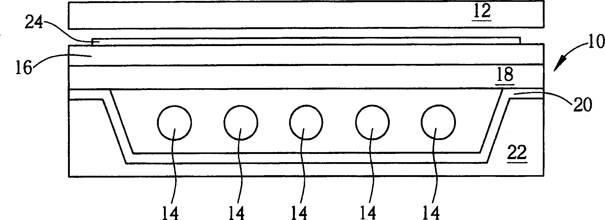
The technology of a backlight module and a light source module, which is applied in the directions of optics, nonlinear optics, identification devices, etc., can solve the problems of uneven illumination intensity, poor display quality of the display panel 12, and uneven distribution of illumination intensity, etc., so as to improve product quality. Competitiveness, guaranteed display quality, evenly distributed effects

Inactive Publication Date: 2004-08-25
AU OPTRONICS CORP
View PDF0 Cites 10 Cited by
  • Summary
  • Abstract
  • Description
  • Claims
  • Application Information

AI Technical Summary

Problems solved by technology

However if figure 1 As shown, the reflector 20 located in the central part of the backlight module 10 is horizontally arranged under the light source generator 14, while the reflector 20 located on both sides of the backlight module 10 is arranged on both sides of the backlight module 10 with an inclined plane. Therefore, the light intensity of the light source reflected upward by the reflector 20 and further scattered to the display panel 12 tends to present an uneven distribution, resulting in poor display quality of the display panel 12.
In addition, based on the consideration of production cost or other factors, the light source generators 14 used in the backlight module 10 may not be of the same specification, and the light sources generated may not have the same brightness, which further aggravates the difference in light intensity. average problem

Method used


Image

  • Backlight module
  • Backlight module
  • Backlight module

Examples


Embodiment Construction

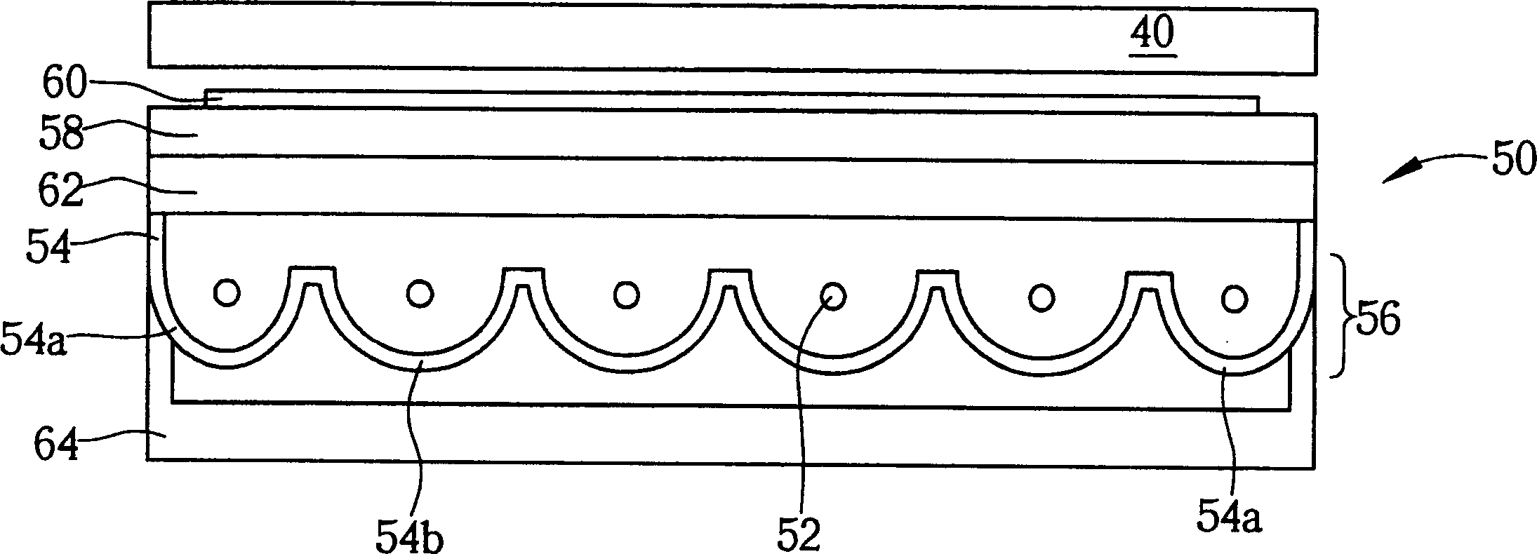
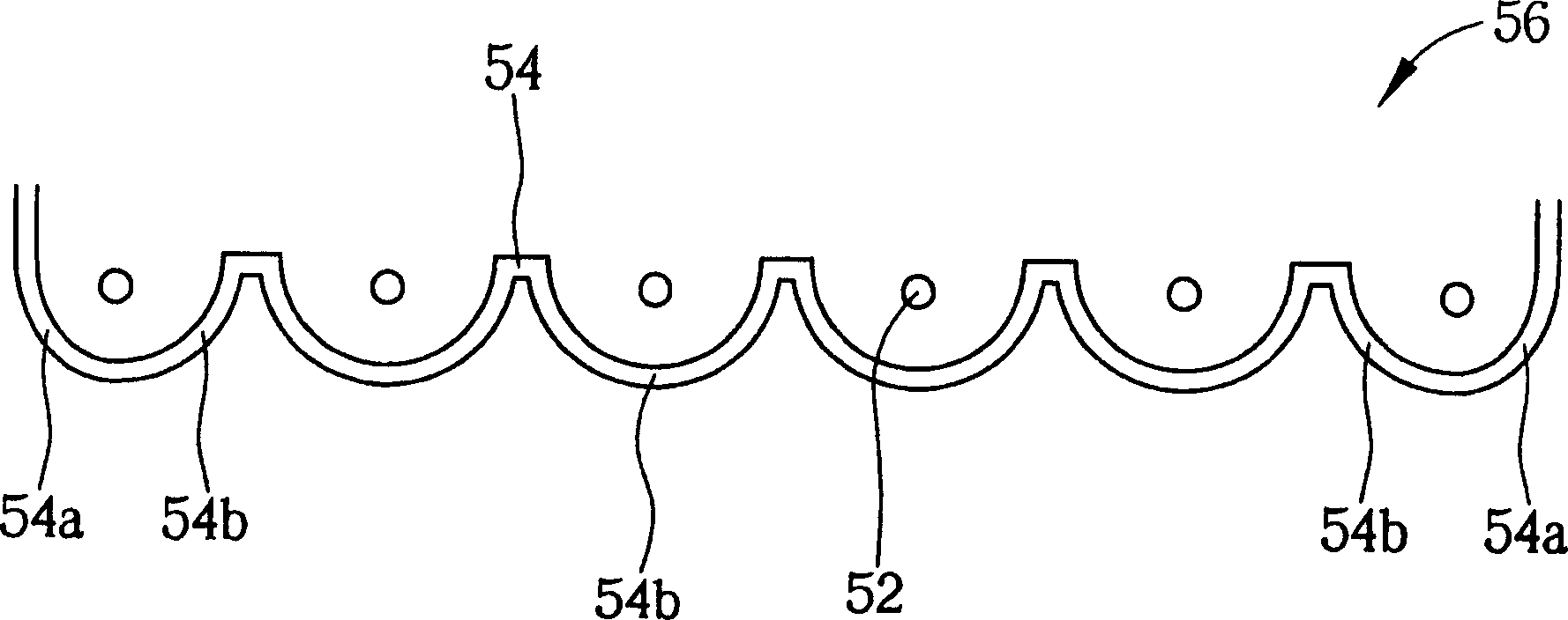
[0022] Please refer to figure 2 , figure 2 It is a schematic cross-sectional view of a back light module 50 of the present invention. Such as figure 2 As shown, the backlight module 50 is arranged below a display panel (display panel) 40, and the backlight module 50 includes a reflective plate ( A light source module (light source unit) 56 composed of a reflecting sheet 54, a diffusing plate (diffusing plate) 58 disposed between the light source generator 52 and the display panel 40, at least one prism (prism) 60 disposed on the surface of the diffusing plate 58 , a light guide plate (LGP) 62 disposed between the light source generator 52 and the diffuser plate 58 , and a housing (housing) 64 disposed below the reflective plate 54 and wrapping around the reflective plate 54 .

[0023] The light source generators 52 are lamp tubes arranged in parallel to provide a light source (not shown), and the reflector 54 is used to reflect the light source upward to the display pane...


PUM


Abstract

The invention is a backlight module, set under a display panel and containing a light source unit, a diffusing plate, at least a prism, a light guide plate (LGP) and a housing. The light source unit contains at least a light source generator to provide a light source and a reflecting sheet set under the light source generator and containing at least a first curve and at least a second curve.

Description

technical field [0001] The present invention provides a back light module, especially a reflecting sheet comprising at least one first curved surface and at least one second curved surface, so that the first curved surface and the second curved surface can be used to Two curved surfaces are used to compensate the backlight module for display brightness. Background technique [0002] The backlight module is one of the key components of LCD products, and has been commonly used in digital cameras, digital personal assistants (PDAs), satellite navigation systems, computer monitors and flat-screen TVs. Generally speaking, the backlight module is arranged under a display panel, and has a light source and a diffusing plate, so as to provide a uniformly dispersed light to the display panel, and then control the display panel On the pixel electrode to form the appropriate image. Wherein, the backlight module can be divided into a direct illuminance backlight module whose light sour...

Claims


Application Information

Patent Timeline
Patent Type & Authority Applications(China)
IPC IPC(8): G02F1/13357G09F9/35
Inventor 傅世泽杨金城
Owner AU OPTRONICS CORP
Features
  • R&D
  • Intellectual Property
  • Life Sciences
  • Materials
  • Tech Scout
  • Unparalleled Data Quality
  • Higher Quality Content
  • 60% Fewer Hallucinations
Learn More