
Liquid crystal display device and backlight module thereof

A backlight module and light source technology, applied in lighting devices, fixed lighting devices, optics, etc., can solve the problems of mechanism parameter tolerance, influence on the brightness of backlight modules, assembly deviation, etc., and achieve good luminous brightness and design value, luminous brightness Compared with the design value, the effect of reducing the chance of changing

Active Publication Date: 2013-02-13
TCL CHINA STAR OPTOELECTRONICS TECH CO LTD
View PDF5 Cites 16 Cited by
  • Summary
  • Abstract
  • Description
  • Claims
  • Application Information

AI Technical Summary

Problems solved by technology

[0004] In the long-term research and development, the inventors of the present application found that due to the existence of problems such as structural parameter tolerances of various components, assembly deviations, thermal expansion of the light guide plate, etc., the light coupling distance may deviate from the design value, for example, the light coupling distance deviation Large, which in turn affects the brightness of the backlight module

Method used


Image

  • Liquid crystal display device and backlight module thereof
  • Liquid crystal display device and backlight module thereof
  • Liquid crystal display device and backlight module thereof

Examples


Embodiment Construction

[0025] The technical solutions in the embodiments of the present invention will be clearly and completely described below in conjunction with the accompanying drawings in the embodiments of the present invention. Obviously, the described embodiments are only part of the embodiments of the present invention, not all of them. Based on the implementation manners in the present invention, all other implementation manners obtained by persons of ordinary skill in the art without making creative efforts belong to the scope of protection of the present invention.

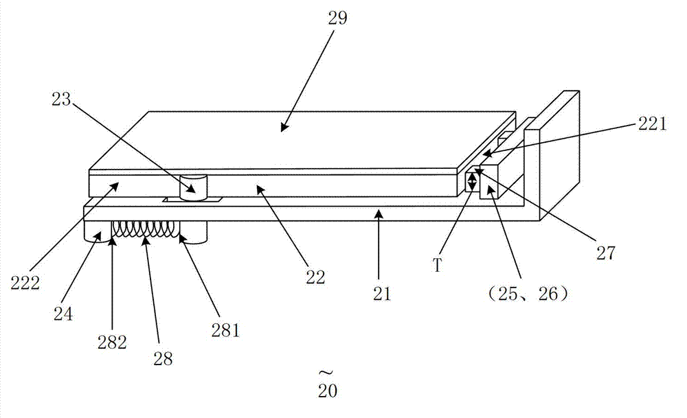
[0026] Please also refer to image 3 , 4 , 5, 6, 7, where image 3 It is a three-dimensional schematic diagram of an embodiment of the backlight module of the present invention; Figure 4 It is a schematic bottom view of the embodiment of the backlight module of the present invention; Figure 5 It is a schematic top view of the embodiment of the backlight module of the present invention; Figure 6 yes Figure 5 Enlarge...


PUM


Abstract

The invention discloses a backlight module. The backlight module comprises a substrate, a light guide plate, a first column body, light sources, a spacer and an elastic component, wherein the light guide plate is arranged on the substrate; a light-emitting device of each light source is arranged toward a first side edge of the light guide plate; by the adoption of the spacer, a minimum distance is reserved between the first side edge of the light guide plate and the light-emitting device of each light source; at least part of the first column body is fixed on the light guide plate; a first end of the elastic component is connected to the end, which penetrates through a slit of the substrate, of the first column body; a second end of the elastic component is connected to the substrate; compared with the first end of the elastic component, the second end of the elastic component is further away from the first side edge of the light guide plate; and the elastic component pushes the first column body to drive the light guide plate to move toward the light sources until the distance between the light guide plate and the light emitting device of each light source reaches the minimum distance. The invention also discloses a liquid crystal display device. By the backlight module and the liquid crystal display device, the possibility that the distance of coupled light changes is reduced, and the luminance of the module is kept consistent with a design value well.

Description

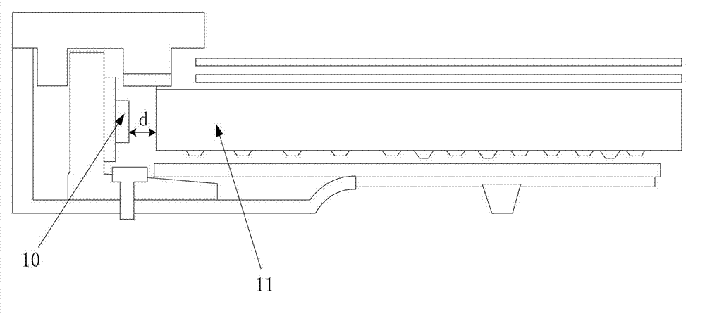
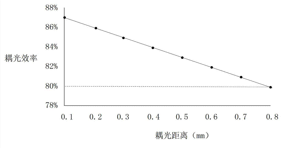
technical field [0001] The invention relates to the technical field of liquid crystal display, in particular to a liquid crystal display device and a backlight module thereof. Background technique [0002] In the side-type LED backlight module, the light coupling efficiency is an important factor affecting the brightness of the backlight module, and the light coupling efficiency is the efficiency with which the light energy of the LED is transmitted into the light guide plate. The light coupling efficiency is related to the light coupling distance, and the light coupling distance is the distance between the end surface of the light-emitting surface of the LED and the end surface of the light-incoming surface of the light guide plate. [0003] refer to figure 1 , figure 1 It is a schematic cross-sectional view of a side-in LED backlight module in the prior art, and the distance d between the LED 10 and the light guide plate 11 is the light coupling distance. Different ligh...

Claims


Application Information

Patent Timeline
Patent Type & Authority Applications(China)
IPC IPC(8): F21S8/00F21V8/00G02F1/13357F21Y101/02
CPCG02B6/0088G02F1/1333G02B6/0091G02F1/133615
Inventor 苏赞加
Owner TCL CHINA STAR OPTOELECTRONICS TECH CO LTD
Learn More