Method and apparatus for determining acetabular component positioning

a technology for acetabular components and positioning methods, applied in the direction of prosthesis, instruments, osteosynthesis devices, etc., can solve the problems of small errors in the orientation of the acetabular component, and the inability to reliably use local acetabular anatomy in the position determination of the prosthetic acetabular componen

Active Publication Date: 2009-12-10
MURPHY STEPHEN B
View PDF12 Cites 110 Cited by
  • Summary
  • Abstract
  • Description
  • Claims
  • Application Information

AI Technical Summary

Benefits of technology

[0022]In still another implementation, the leg that is positioned at P1 is a hollow leg that slides over a guide pin that is drilled or screwed into the bone at P1. In use, the surgeon first fixes the guide pin into the bone at the desired locati

Problems solved by technology

Conversely, if that relationship is not known, the local acetabular anatomy may not reliably be used in determining the position of the prosthetic acetabular component.
Second, parts of the hemipelvis ar

Method used


Image

  • Method and apparatus for determining acetabular component positioning
  • Method and apparatus for determining acetabular component positioning
  • Method and apparatus for determining acetabular component positioning

Examples


Embodiment Construction

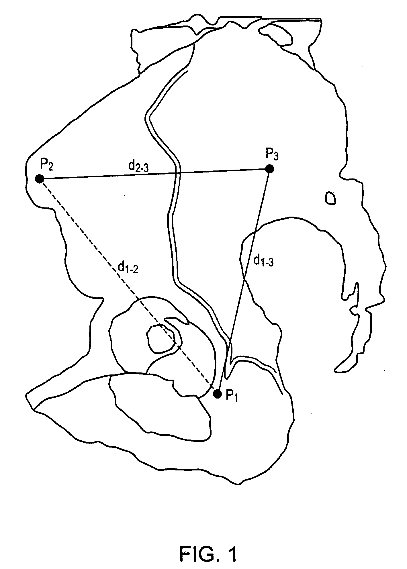
[0030]FIG. 1 is schematized view of a right pelvis showing the three points in question. Distance d1-2 is the distance between the first point, P1, (a point located on the ischium as it joins the posterior wall of the acetabulum) and the second point, P2, a point located on the lateral surface of the iliac wing, immediately adjacent to the anterior superior iliac spine. Distance d1-3 is the distance between the first point, P1, and the third point, P3 (on the ilium); and distance d2-3 is the distance between the second point, P2 and third point P3. The distance d1-2 is the baseline; the distances d1-3 and d2-3 are set at a distance of from 70% to 100% of the baseline distance, preferably about 80-90%. In FIG. 1 they are shown as being approximately 80-85% of the baseline distance. In FIG. 1, distances d1-3 and d1-3 are shown as approximately of equal length, although, as noted above, they need not necessarily be so. These three points, P1, P2, and P3 define an ipsilateral plane.
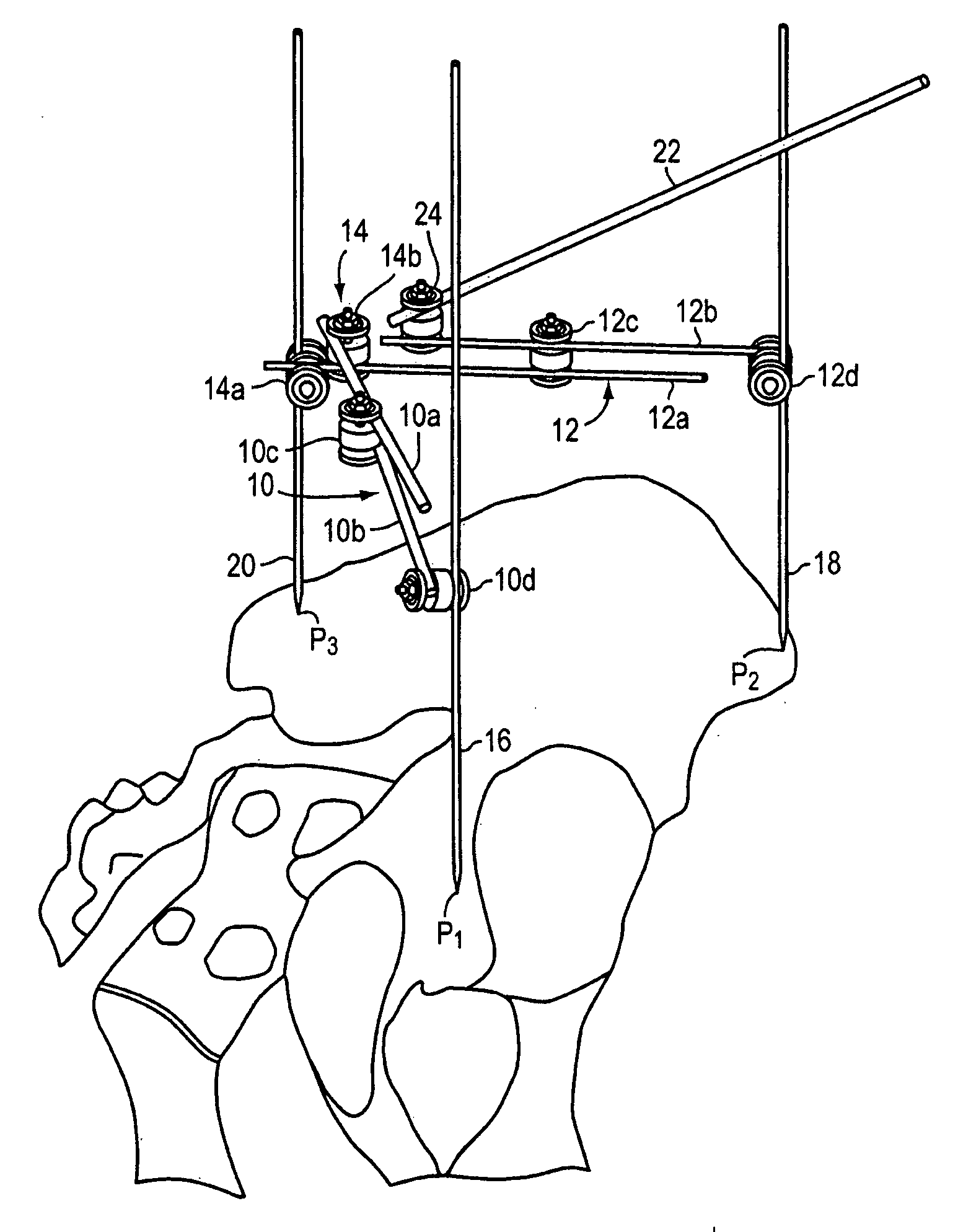
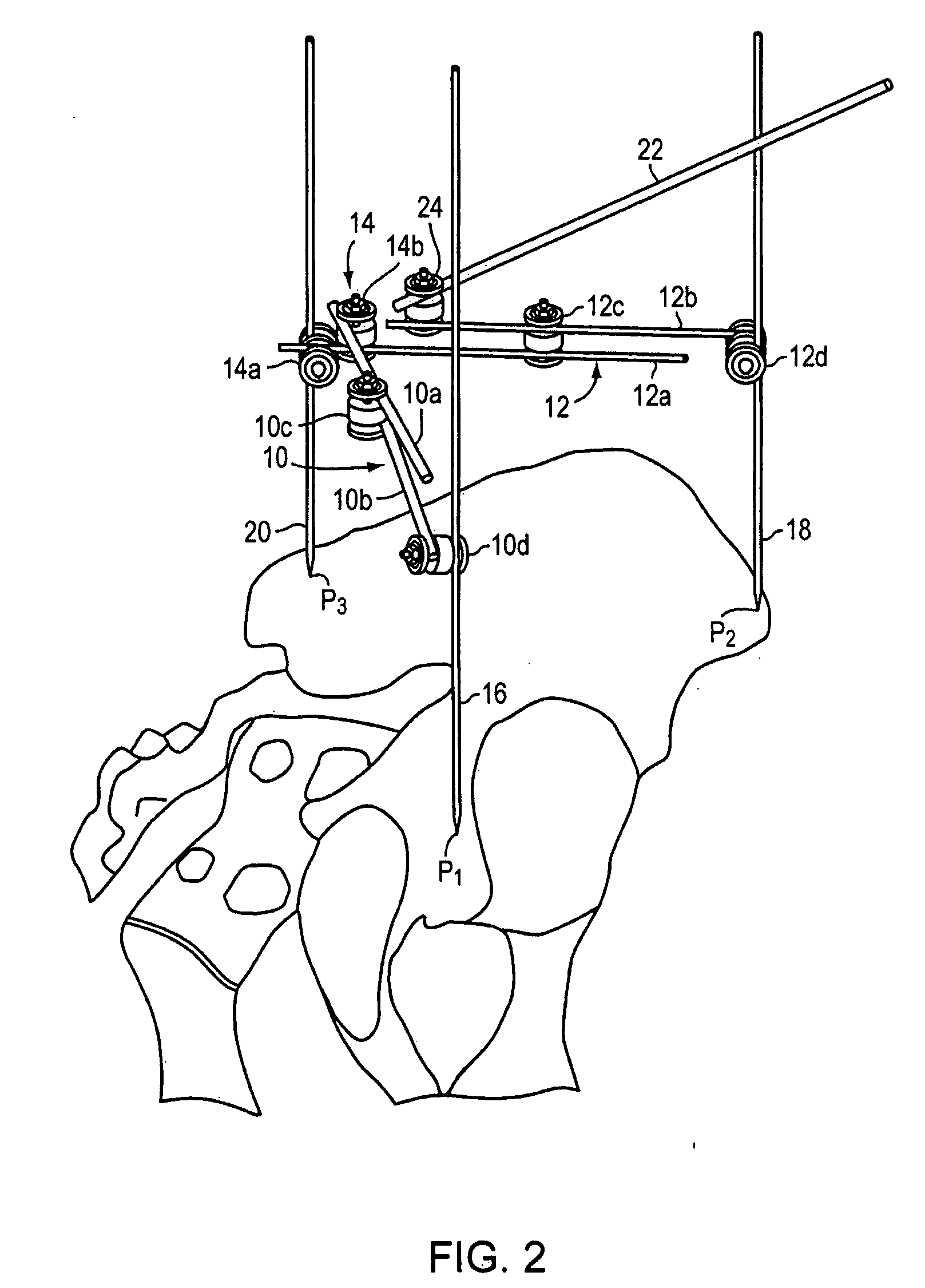
[003...


PUM

PropertyMeasurementUnit
Fractionaaaaaaaaaa
Fractionaaaaaaaaaa
Fractionaaaaaaaaaa

Abstract

An instrument for establishing orientation of a pelvic prosthesis comprises a tri-pod having an angularly adjustable guide rod on it. The tips of the legs define a plane, and the guide rod is set by the surgeon to a defined orientation with respect to this plane on the basis of preoperative studies. In use, two of the legs of the instrument are positioned by the surgeon at defined anatomical locations on the pelvis (e.g., a point in the region of the posterior/inferior acetabulum and a point on the anterior superior iliac spine). The third leg then lands on the pelvis at a point determined by the position of the first two points, as well as by the separations between the third leg and the other two legs. The separations are adjustable, but are preferably fixed percentages of the separation between the first and second legs. The position of the guide rod then defines with respect to the actual pelvis the direction for insertion of a prosthesis.

Description

FIELD OF THE INVENTION[0001]The invention relates to determining acetabular component positioning, and provides a method and apparatus for rapidly and accurately determining such positioning.BACKGROUND INFORMATION[0002]Malpositioning of the acetabular component during hip arthroplasty can lead to dislocation, impingement, wear, and reoperation for all of these problems. Proper positioning of the acetabular component during hip arthroplasty requires that the surgeon know the position of the patient's pelvis during surgery so that the component can be inserted in proper position relative to the pelvis. Unfortunately, the position of the patient's pelvis varies widely during surgery and from patient to patient. As a result, large errors in component positioning occur if the surgeon assumes that the patient's pelvis is positioned squarely with the operating table, whether in the lateral or supine position. For example, one study showed that patients' pelvises were malpositioned through ...

Claims


Application Information

Patent Timeline
IPC IPC(8): A61B19/00A61B17/58
CPCA61B19/46A61B19/201A61B2019/5289A61B19/50A61B17/1746F16C2316/10A61K45/06F16C11/103A61B90/11A61B2090/067A61B2090/364A61K31/409A61K31/44A61K31/555Y10T403/32426A61K2300/00A61B90/00A61B17/56A61F2/32A61F2/46G16Z99/00A61B5/107A61B5/1071A61B5/1072A61B5/1114A61B17/00A61B17/17B43L7/10G01B3/563G01B3/56G01B5/24F16C11/10A61F2/4609A61B90/06A61B34/10A61B2034/105
Inventor MURPHY, STEPHEN B.
Owner MURPHY STEPHEN B
Why Eureka
Try Eureka