
Vehicle control apparatus

a technology of vehicle control and control apparatus, which is applied in the direction of vehicle position/course/altitude control, process and machine control, instruments, etc., can solve the problems of low vehicle speed, vehicle cannot autonomously travel within a travelling lane on a curved road, and the estimated position of the vehicle is large, and suppresses interference. , the effect of reducing the error of longitudinal position

Active Publication Date: 2019-06-04
TOYOTA JIDOSHA KK
View PDF24 Cites 13 Cited by
  • Summary
  • Abstract
  • Description
  • Claims
  • Application Information

AI Technical Summary

Benefits of technology

The present disclosure provides a vehicle control apparatus that can control the speed of a vehicle when entering a curved road, even if there is an error in the estimated position of the vehicle. The apparatus uses a curve travel speed calculation unit and a speed control unit to adjust the vehicle speed based on the error in longitudinal position. This allows the vehicle to autonomously travel within the driving lane on the curved road. Additionally, the apparatus allows for a hands-on request by the driver in case of a lower curve travel speed, which can help the driver maintain control and safely drive the vehicle through the curve. The apparatus also calculates a reference distance to determine the appropriate time for the driver to perform the hands-on request. Overall, this technology ensures safe and efficient driving through curved roads.

Problems solved by technology

Here, there is an error (a deviation) in the estimated position of the vehicle.
An error in longitudinal position is an example of an error in longitudinal position of the vehicle.
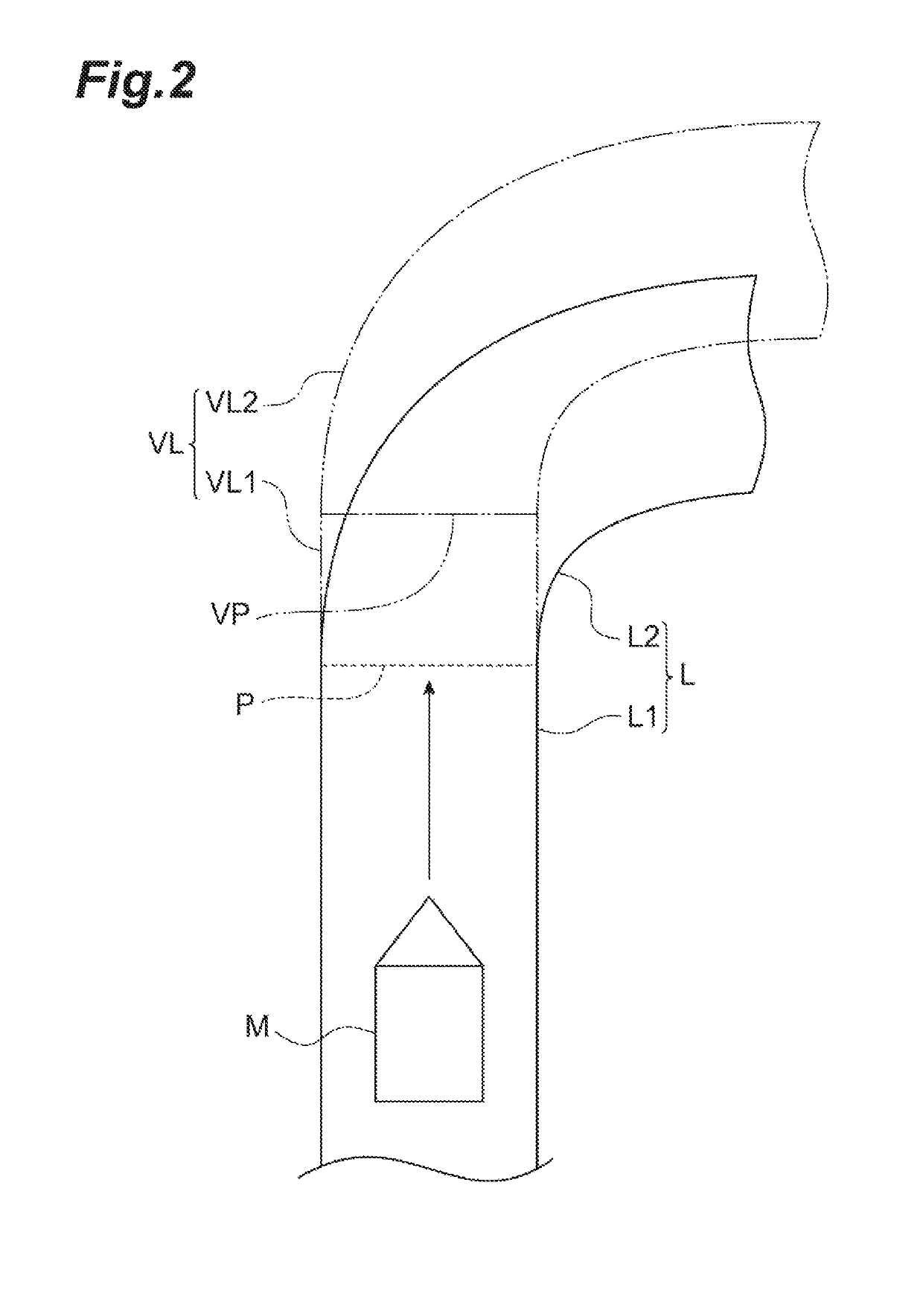
When this error in longitudinal position is large, in a case where the vehicle enters a curved road from a straight road, depending on a vehicle speed, it can be considered that the vehicle cannot autonomously travel within a travelling lane on the curved road.
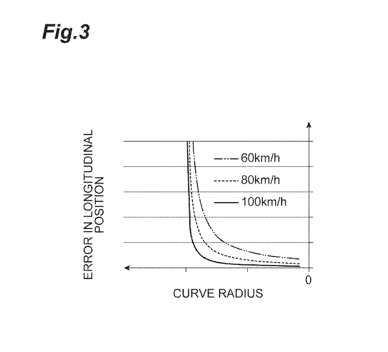
In this way, in a case where the error in longitudinal position is large, the vehicle speed becomes low compared to a case where the error is small.

Method used


Image

  • Vehicle control apparatus
  • Vehicle control apparatus
  • Vehicle control apparatus

Examples


Embodiment Construction

[0015]Hereinafter, an embodiment of the present disclosure will be described with reference to the drawings. In the description of the drawings, the same reference signs will be given to the same elements and the descriptions thereof will not be repeated.

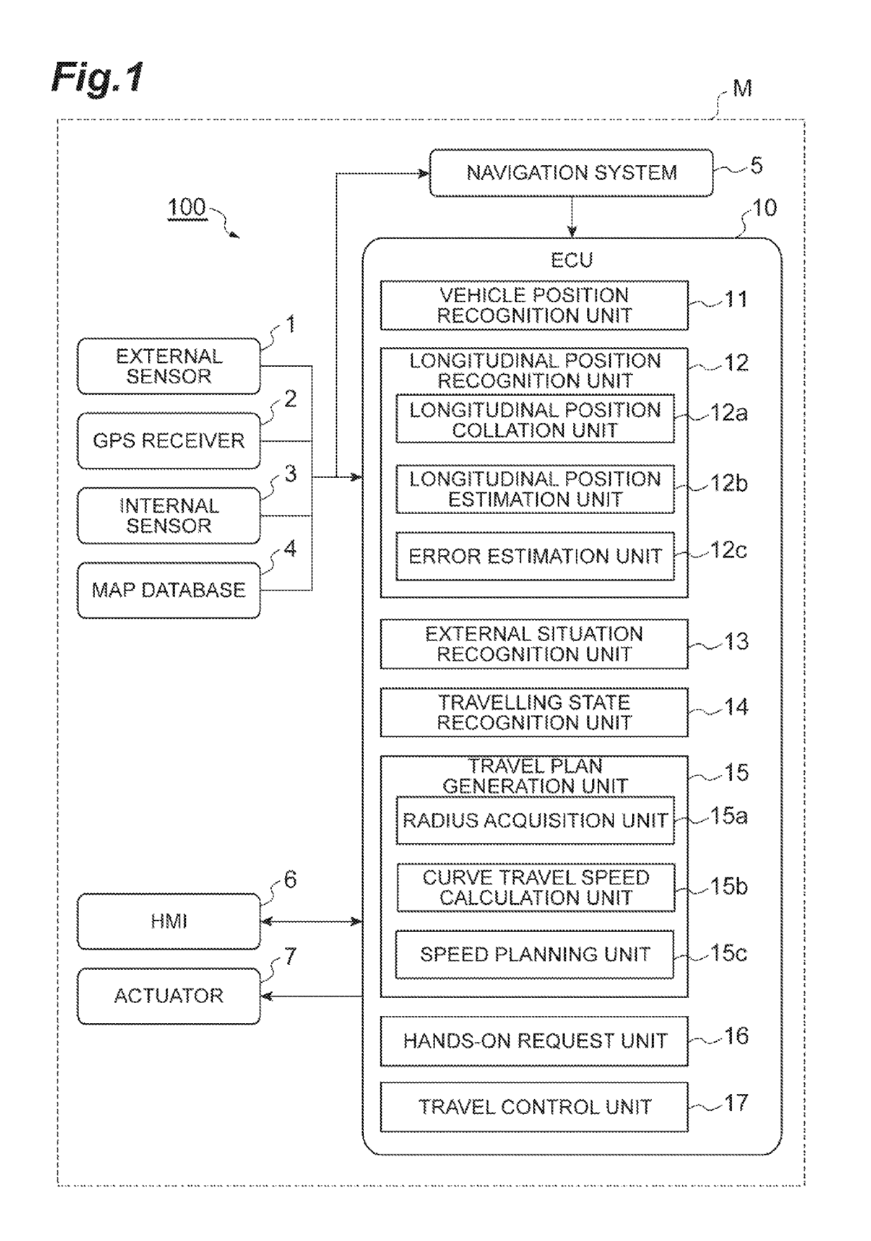
[0016]As illustrated in FIG. 1, a vehicle control apparatus 100 is mounted on a vehicle M such as a passenger car and performs a control (an autonomous driving control) such that the vehicle M autonomously travels, on which the vehicle control apparatus 100 is mounted. The vehicle control apparatus 100 includes an external sensor 1, a global positioning system (GPS) receiver 2, an internal sensor 3, a map database 4, a navigation system 5, an HMI 6, an actuator 7, and an electronic control unit (ECU) 10.

[0017]The external sensor 1 is a detection device that detects a situation around the vehicle M. The external sensor 1 includes a camera and a radar sensor.

[0018]The camera is an imaging device that images external situations of the ...


PUM


Abstract

To control a speed at a time of entering a curved road a vehicle to autonomously travel within a travelling lane even in a case where there is an error in an estimated longitudinal position of the vehicle.A curve travel speed calculation unit 15b calculates a curve travel speed for a vehicle to autonomously travelling in a travelling lane based on a curve radius and an estimated error in longitudinal position. A speed planning unit 15c and a travel control unit 17 decelerate the vehicle M such that the speed of the vehicle M becomes the curve travel speed at the time of entering the curved road in front of the vehicle M in a case where the speed of the vehicle M is equal to or higher than the curve travel speed and the curve travel speed is equal to or higher than the reference speed.

Description

CROSS-REFERENCE TO RELATED APPLICATION[0001]This application claims priority to Japanese Patent Application No. 2016-164896 filed on Aug. 25, 2016, the entire contents of which are hereby incorporated by reference.TECHNICAL FIELD[0002]The present disclosure relates to a vehicle control apparatus.BACKGROUND[0003]A vehicle control apparatus that performs a control of a vehicle is disclosed in, for example, Japanese Unexamined Patent Publication No. 2015-178332. The vehicle control apparatus disclosed in Japanese Unexamined Patent Publication No. 2015-178332 estimates a position of the vehicle based on detected lane lines, and causes the vehicle to autonomously travel based on the estimated position.SUMMARY[0004]Here, there is an error (a deviation) in the estimated position of the vehicle. An error in longitudinal position is an example of an error in longitudinal position of the vehicle. When this error in longitudinal position is large, in a case where the vehicle enters a curved ro...

Claims


Application Information

Patent Timeline
IPC IPC(8): G05D1/02B60W50/08B60W50/14G05D1/00B60W30/14B60W30/18
CPCG05D1/0223B60W30/143B60W30/18145B60W50/082B60W50/14G05D1/0246G05D1/0274G05D1/0061G05D2201/0213B60W2420/42B60W2550/146G05D1/0251G05D1/0257G05D1/0276G05D1/0278B60W2552/30B60W2420/403B60W60/0059B60W2556/20B60W60/0053B60W2552/53B60W60/0057B60W2720/103B60W2520/14B60W2520/125B60W2520/10B60W2520/105B60W2420/408
Inventor KUNISA, AKIOMIMATSUI, TOSHIKINEMOTO, YUSUKETAKAHASHI, NORIHIRO
Owner TOYOTA JIDOSHA KK
Learn More