Power window system and method for controlling power-operated window

a technology of power window and power window, which is applied in the direction of motor/generator/converter stopper, dynamo-electric converter control, instruments, etc., can solve the problems of reducing the windowpane, reducing the windowpane, and reducing the error of position due to the inertia of the windowpan

Active Publication Date: 2006-11-16
HONDA MOTOR CO LTD
View PDF14 Cites 17 Cited by
  • Summary
  • Abstract
  • Description
  • Claims
  • Application Information

AI Technical Summary

Benefits of technology

[0015] In an alternative embodiment, the first position of the windowpane to be stored in the memory may be derived at expiration of a predetermined period of time after an instant when the controller has recognized that the supply voltage for the motor has dropped below the predetermined level during the movement of the windowpane. With this configuration, the possibility of an error in position due to the inertia of the windowpane can be reduced.

Problems solved by technology

In such a power window system, during an automatic upward movement (AUTO-UP motion) of a windowpane, triggered by an activation of a CLOSE switch and continued with a driving force (mechanical power) provided by a motor, an obstacle may happen to come in a gap between an upper edge of the windowpane and an upper sash of the door (or roof side rail of the vehicle in an instance where the window is sashless) and possibly be trapped in the gap as the windowpane moves up.
On the other hand, to render the discussion complete, consideration may have to be given to the fully closed position of the windowpane in conjunction with the trap detection during closing operation of the window (while the windowpane is rising), in that the trap detection would occur in response to the load that could be placed to the motor when the windowpane has risen to the fully closed position, which would cause the motor to be reversed (reversely rotated), and thus lower the windowpane even if no obstacle is trapped in the window, with the result that one would become unable to fully close the window.
For that purpose, however, a large-capacitance capacitor capable of supplying energy much enough for writing operation into the memory would disadvantageously be required under the conventional scheme, leading to an undesired increase in the cost of implementing the system.

Method used


Image

  • Power window system and method for controlling power-operated window
  • Power window system and method for controlling power-operated window
  • Power window system and method for controlling power-operated window

Examples


first embodiment

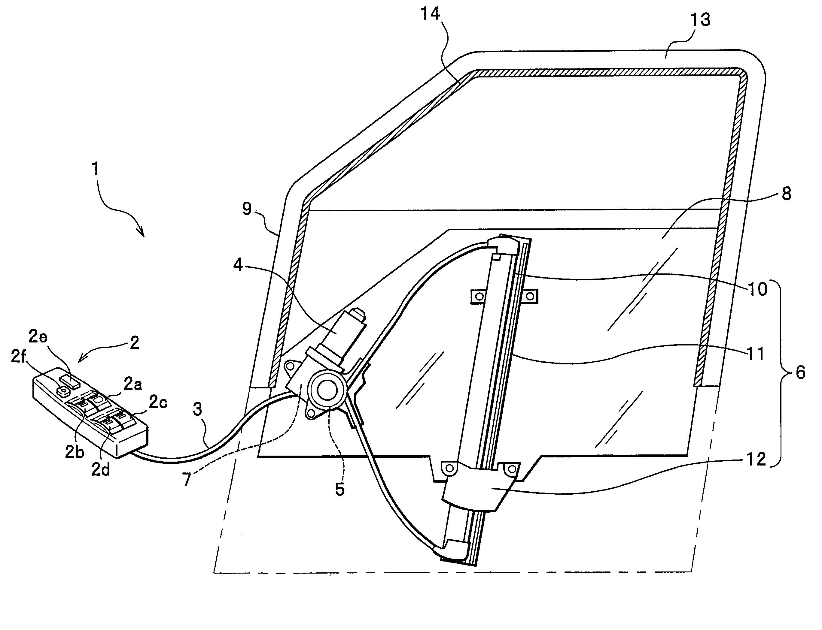
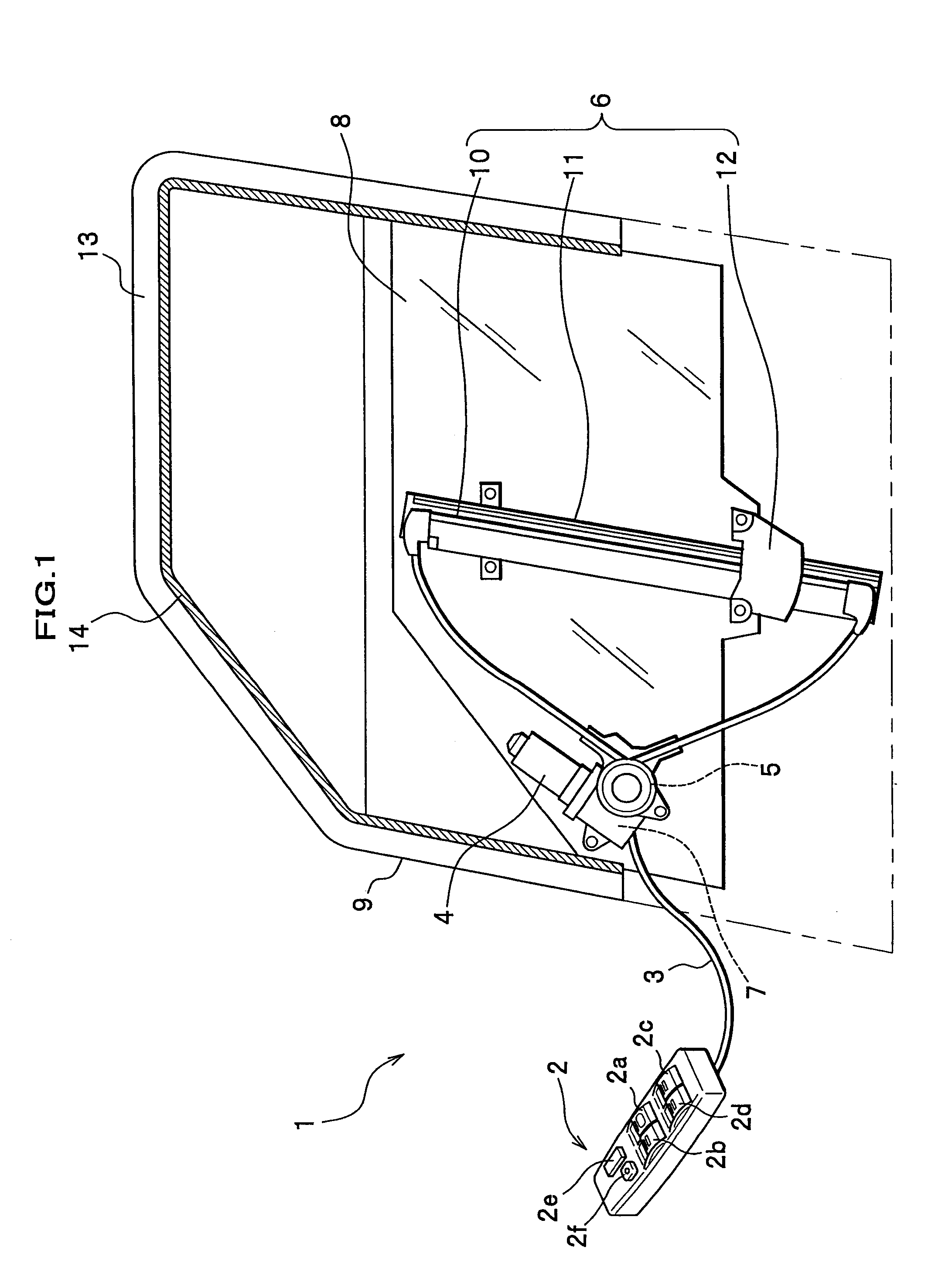
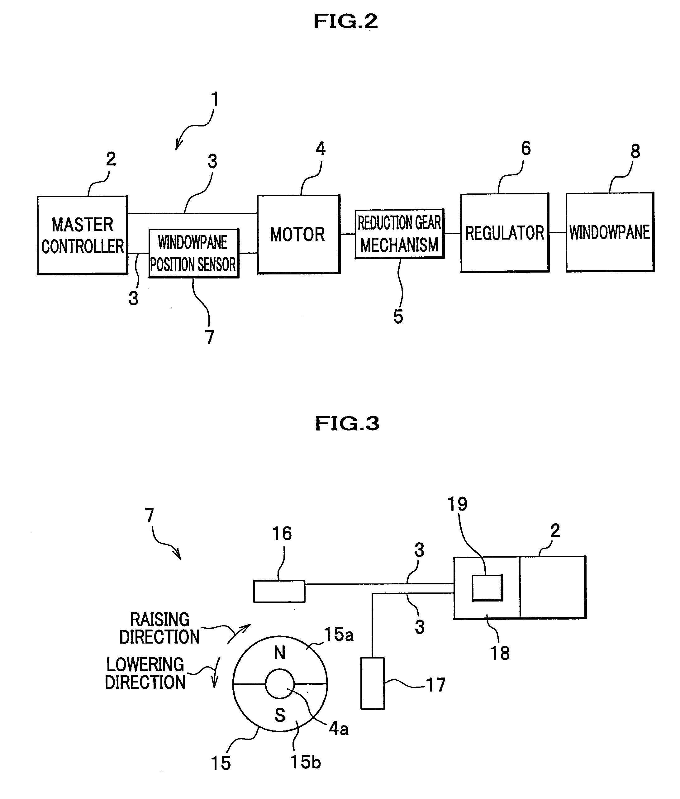
[0031] As shown in FIGS. 1 and 2, a power window system 1 according to the first embodiment includes a master controller 2, a harness 3, a motor 4, a reduction gear mechanism 5, a regulator 6, a windowpane position sensor 7 and a windowpane 8. The master controller 2 is provided in an arm rest (not shown) of a door 9 at a driver's seat. The motor 4, the reduction gear mechanism 5 and the windowpane position sensor 7 that are combined together with the regulator 6 in a single unit are fixed on a door inner panel (not shown) of the door 9. The regulator 6 includes a wire 10, a guide rail 11 and a carrier plate 12. In FIG. 1, the windowpane 8 has been moved down to the extremity and the door 9 is fully opened. Illustrated in FIG. 1 is the power window system 1 including a power window provided in the door 9 at the front seat driver's side; however, a front seat passenger side door, and rear seat right and left side doors, for example, of a four-door vehicle also incorporate a power win...

second embodiment

[0058] Referring now to a flowchart illustrated in FIG. 8, a control process exercised when the battery voltage lowers below a predetermined level will be described in connection with the power window system 1 according to a second embodiment of the present invention. In this embodiment, all the steps (S1-S10) except step S″ in FIG. 8 are the same as those of the first embodiment shown in FIG. 5, and thus a duplicated description will be omitted herein.

[0059] In this embodiment, after the control unit 18 transmits a stop signal to the motor 4 to stop the rotation of the motor 4 in step S4, the control unit 18 waits a predetermined period of time, e.g., 20 ms or so (step S4'), and at a moment of expiration of the predetermined period of time, the control unit 18 writes, in the EEPROM 19 of the control unit 18, position data of the windowpane 8, a direction of rotation of the motor 4 (corresponding to a motion direction of the windowpane 8) and a pulse level based upon the pulse sign...


PUM


Abstract

If a supply voltage for a motor drops below a predetermined level during movement of a windowpane, a controller of a power window system outputs a stop signal instructing the motor to stop rotating, and stores in a memory a first position and a motion direction of the windowpane derived from a first signal generated by a transducer (signal generator). The controller compares a second position of the windowpane derived from a second signal generated by the transducer when the supply voltage for the motor is restored to the predetermined level or higher with the first position of the windowpane stored in the memory. If the second position is different from the first position, the first position stored in the memory is corrected toward the motion direction by an amount corresponding to a difference between the first and second positions

Description

BACKGROUND OF THE INVENTION [0001] This invention relates generally to power window systems and methods for controlling a power-operated window, and more particularly to a power window system or electric-motor driven mechanism which electrically actuates a regulator (windowpane lift mechanism) to open and close a window (lower and raise a windowpane or window glass) of a vehicle. [0002] Many vehicles are equipped with a power window system in recent years. The power window system is adapted to move down and up a windowpane (to open and close a window) provided in each door of a vehicle, by switching rotation of a motor between normal and reverse directions. Typically, activation of an OPEN switch causes a DOWN motion of a relevant windowpane toward a fully opened position, while activation of a CLOSE switch causes an UP motion of a relevant windowpane toward a fully closed position. In such a power window system, during an automatic upward movement (AUTO-UP motion) of a windowpane, ...

Claims


Application Information

Patent Timeline
Patent Type & Authority Applications(United States)
IPC IPC(8): E05F11/48
CPCE05Y2400/342E05Y2400/512E05Y2400/612E05F15/695E05Y2900/55E05F15/41E05Y2600/454
Inventor NORO, YOSHIKISHIOIRI, KENJI
Owner HONDA MOTOR CO LTD
Why Eureka
Try Eureka