Liquid crystal display panel and display device

A liquid crystal display panel, display area technology, applied in nonlinear optics, instruments, optics, etc., can solve the problems of uneven display, screen flicker, high power consumption, etc., achieve enhanced effect, consistent brightness and contrast, and large privacy The effect of the angle

Active Publication Date: 2018-12-28
KUSN INFOVISION OPTOELECTRONICS
View PDF4 Cites 15 Cited by
  • Summary
  • Abstract
  • Description
  • Claims
  • Application Information

AI Technical Summary

Problems solved by technology

Because when displaying at a narrow viewing angle, the voltage applied to the viewing angle control electrode is generally an AC voltage, and the load is large, and the coupling between the viewing angle control electrode and the pixel electrode causes screen flicker and display unevenness (mura)
In order to solve this problem, the existing technology reduces the flickering of the screen by increasing the frame frequency of the liquid crystal display device to 120Hz, but this will cause the problem of excessive power consumption

Method used


Image

  • Liquid crystal display panel and display device
  • Liquid crystal display panel and display device
  • Liquid crystal display panel and display device

Examples


no. 1 example

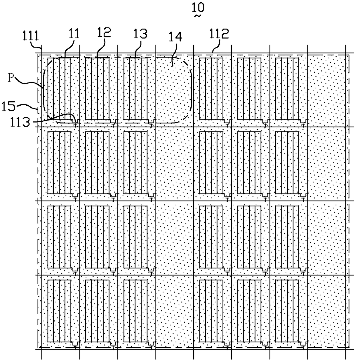
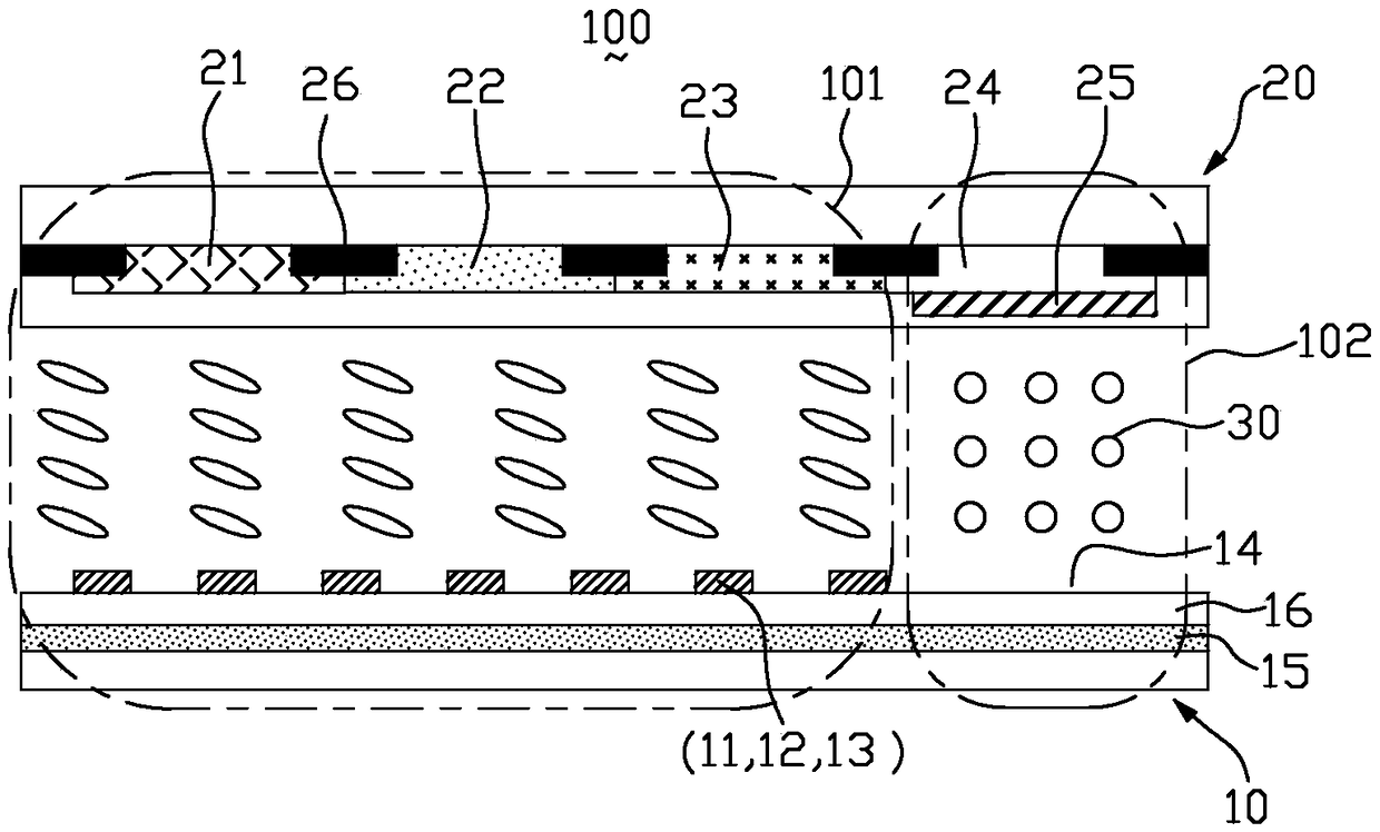
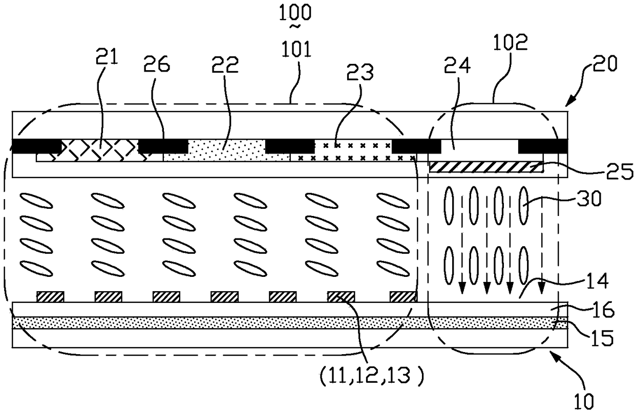
[0036] figure 1 It is a schematic plan view of the first substrate 10 in the liquid crystal display panel according to the first embodiment of the present invention. figure 2 It is a schematic cross-sectional view of the liquid crystal display panel in the wide viewing angle mode according to the first embodiment of the present invention. image 3 It is a schematic cross-sectional view of the liquid crystal display panel in the narrow viewing angle mode according to the first embodiment of the present invention. Please refer to Figure 1 to Figure 3, the present embodiment provides a liquid crystal display panel 100, the liquid crystal display panel 100 includes a first substrate 10 and a second substrate 20 disposed opposite to each other, and a liquid crystal interposed between the first substrate 10 and the second substrate 20 Layer 20. The liquid crystal display panel 100 includes a plurality of pixel units P, each pixel unit P includes a display area 101 and a viewing...

no. 2 example

[0056] Please refer to Figure 6 to Figure 7B The main difference between the liquid crystal display panel 100 of this embodiment and the above-mentioned first embodiment is that: in this embodiment, the viewing angle control region 102 includes first electrodes 142 and second electrodes 27 arranged at intervals, wherein the first electrodes 142 and One of the second electrodes 27 is a viewing angle control electrode, the first electrode 142 is located on the first substrate 10, the second electrode 27 is located on the second substrate 20, the first electrode 142 and the second electrode 27 are disposed correspondingly up and down, and the first electrode 142 and the second electrode 27 are strip electrodes.

[0057] In wide viewing angle mode, such as Figure 7A As shown, no voltage is applied to the first electrode 142 and the second electrode 27, that is, the viewing angle control area 102 does not generate an electric field, the liquid crystal molecules remain flat, and ...

no. 3 example

[0061] Please refer to Figure 8The difference between the liquid crystal display panel 100 provided by the third embodiment of the present invention and the above-mentioned second embodiment is that, in this embodiment, the first electrode 142 is a viewing angle control electrode, and the first electrode 142 has a comb structure, The first electrode 142 includes a plurality of comb-tooth portions 144 and a connecting portion 146 vertically connected thereto. The connecting portions 144 and the comb-tooth portions 146 are arranged on the same layer.

[0062] For other structures and working principles of this embodiment, reference may be made to the above-mentioned first embodiment, which will not be repeated here.


PUM


Abstract

The invention provides a liquid crystal display panel. The liquid crystal display panel comprises a first substrate and a second substrate which are oppositely arranged, a liquid crystal layer sandwiched between the first substrate and the second substrate, and a plurality of pixel units P. Each of the pixel units P comprises a display region and a view angle control region. The area of the view angle control region is at least 1/4 of the area of the pixel unit P. The view angle control region is provided with a view angle control electrode. The view angle control region does not generate an electric field, and the liquid crystal display panel is displayed at a wide view angle when the view angle control electrode is not applied with a voltage. The view angle control region generates a vertical electric field, and the liquid crystal display panel is displayed at a narrow view angle when the view angle control electrode is applied with a view angle control voltage. The invention also relates to a display device.

Description

technical field [0001] The invention relates to the field of display technology, and in particular to a liquid crystal display panel with wide and narrow viewing angles switched. Background technique [0002] Liquid crystal display (liquid crystal display, LCD) has the advantages of good image quality, small size, light weight, low driving voltage, low power consumption, no radiation and relatively low manufacturing cost, and occupies a dominant position in the field of flat panel display. [0003] Currently, liquid crystal display devices are gradually developing toward wide viewing angles. For example, liquid crystal display devices using in-plane switching (IPS) or fringe field switching (FFS) modes can achieve wider viewing angles. The wide viewing angle design allows users to see a complete and undistorted picture from all directions. However, in today's society, people pay more and more attention to protecting their privacy, and there are many things that they don't l...

Claims


Application Information

Patent Timeline
Patent Type & Authority Applications(China)
IPC IPC(8): G02F1/13G02F1/1343
CPCG02F1/1323G02F1/1343
Inventor 柯中乔李红侠陶圆龙李少波黄丽玉刘味
Owner KUSN INFOVISION OPTOELECTRONICS
Why Eureka
Try Eureka